Display device and backlight device

Active Publication Date: 2005-11-24
PANASONIC LIQUID CRYSTAL DISPLAY CO LTD
View PDF9 Cites 60 Cited by
  • Summary
  • Abstract
  • Description
  • Claims
  • Application Information

AI Technical Summary

Benefits of technology

[0029] Further, by using the backlight device of the present invention, it is possible to obtain extremely excellent advantageous effects, including following advantageous effects. That is, compared to a cold cathode fluorescent lamp which uses mercury, it is possible to obtain surface light source light of high uniformity in brightness and chromaticity which is substantially equal to or greater than the uniformity in brightness and chromaticity of the cold cathode fluorescent lamp which uses mercury. Further, it is possible to realize a solid-state light-emitting-element direct backlight, that is capable of emitting light of three colors, whic

Problems solved by technology

These constitute factors which deteriorate the uniformity of the brightness and chromaticity on the backlight illumination surface.
That is, to produce a favorable color mixing, it is necessary to allow the air layer ARL formed between the light emitting di

Method used


Image

  • Display device and backlight device
  • Display device and backlight device
  • Display device and backlight device

Examples


Example

[Embodiment 1]

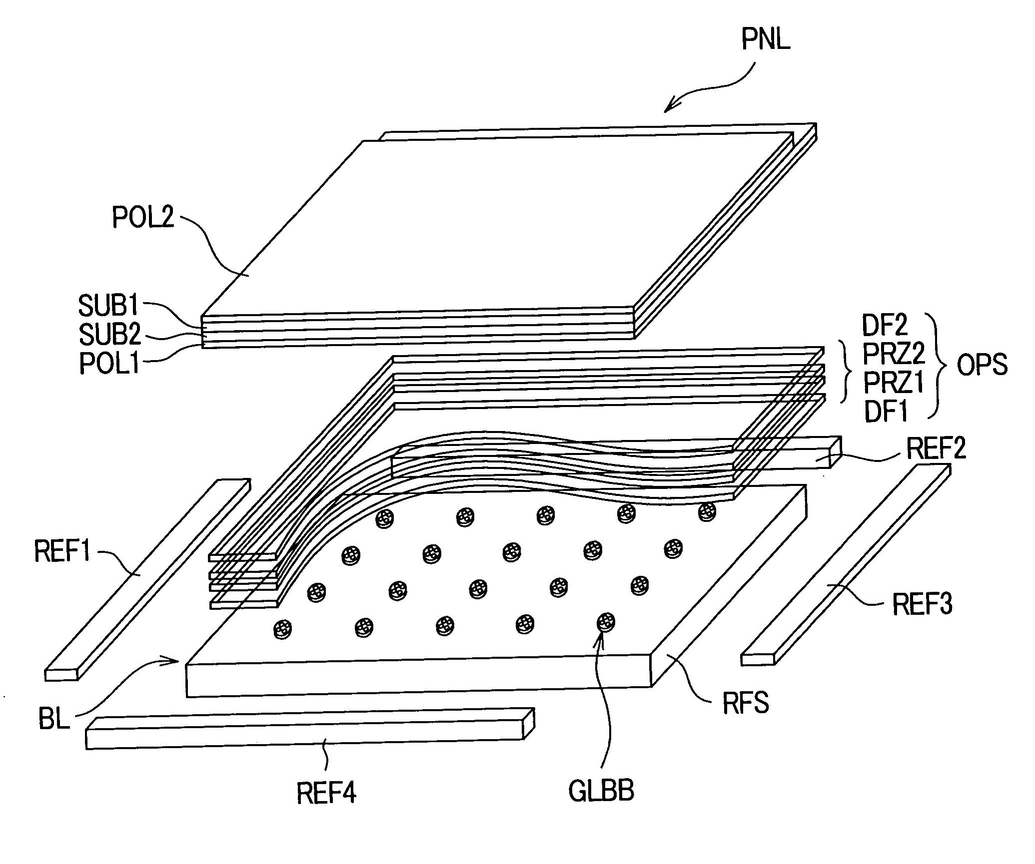
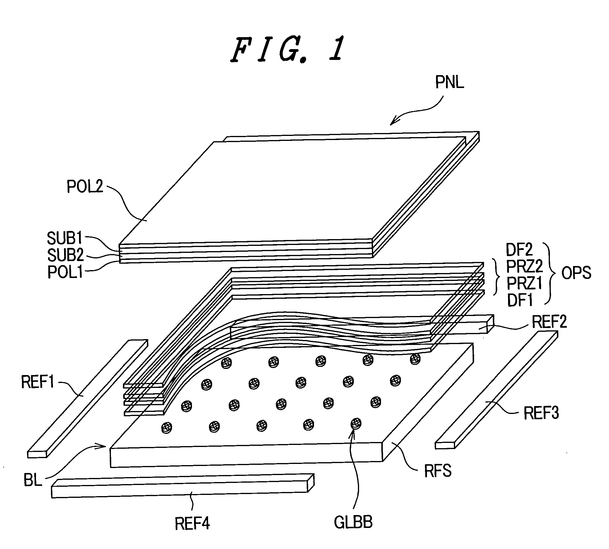
[0044]FIG. 1 is a developed perspective view showing the constitution of an embodiment 1 of a backlight device of the present invention and a liquid crystal display device having the backlight device. In FIG. 1, reference symbol PNL indicates a liquid crystal display panel which constitutes a display panel. In the liquid crystal display panel PNL, a liquid crystal layer is sandwiched between a first substrate SUB1 and a second substrate SUB2, each of which are formed of a light transmitting glass plate. The liquid crystal display panel PNL also includes electrodes, active elements or the like for forming pixels on an inner surface or inner surfaces of either one or both of the light-transmitting-glass first substrate SUB1 and / or second substrate SUB2. Here, the first substrate SUB1 on which the active elements, such as thin film transistors (TFT), are formed is referred to as an active matrix substrate, and can also be referred to as a TFT substrate.

[0045] Further, a...

Example

[Embodiment 2]

[0056]FIG. 5 is an enlarged cross-sectional view of a light guide body block GLBB representing a second embodiment of the backlight device according to the present invention. In the drawing, parts identical to the parts shown in the above-mentioned FIG. 2B are given the same symbols, and a repeated explanation of these parts is omitted. A constitutional feature which makes the constitution shown in FIG. 5 different from the constitution shown in FIG. 2B lies in the fact that a light incident surface GLBI, which is constituted of an inclined surface having an inclination angle α=10°, which increases in opening diameter in the direction toward a reflector REF side, is formed on an inner wall surface of the light guide body GLB, which is formed in a cylindrical shape using a light-transmitting acrylic resin material.

[0057] The shape of the light incident surface GLBI of the cylindrical light guide body GLB, which allows the irradiated light from the light emitting diode...

Example

[Embodiment 3]

[0059]FIG. 6 is an enlarged cross-sectional view of a light guide body block GLBB showing the constitution of an embodiment 3 of the backlight device according to the present invention. In the drawing, parts identical to the parts shown in the above-mentioned FIG. 5 are given the same symbols, and a repeated explanation of these parts is omitted. A constitutional feature which makes the constitution shown in FIG. 6 different from the constitution shown in FIG. 5 lies in the fact that, the light guide body block GLB is constituted in a state such that, for example, prisms PRZ are integrally formed on an outer wall surface of the light guide body GLB, which is formed in a cylindrical shape using a light-transmitting acrylic resin material, to operate as optical control elements having an approximately triangular cross section.

[0060] With such a constitution, when the light L1 which passes through the inside of the light guide body GLB impinges on the outer wall surface...


PUM


Abstract

A backlight device, which uses solid-state light emitting elements capable of emitting lights of three colors, consisting of red, green and blue, can exhibit an enhanced light utilizing efficiency, and can generate light of high uniformity in brightness and chromaticity in a display device which can obtain a display image of high brightness with a rapid response speed. The backlight device includes a reflector which has a light reflection surface, a plurality of light transmitting cylindrical light guide bodies which are mounted on the light reflection surface of the reflector in a uniformly distributed manner, and light emitting diodes capable of emitting lights of at least three colors which are mounted inside each light guide body. By performing color mixing every light guide block, it is possible to obtain a white light of high chromaticity which has a high luminous flux distribution.

Description

CROSS-REFERENCE TO RELATED APPLICATIONS [0001] The disclosure of Japanese Patent Application No. 2004-153182, filed on May 24, 2004, including the specification, drawings and abstract, thereof is incorporated herein by reference in its entirety. BACKGROUND OF THE INVENTION [0002] The present invention relates in general to a backlight device and to a display device which uses the backlight device; and, more particularly the present invention relates to a direct backlight device, which is arranged on a back surface side of a display device, and which uses solid-light-emitting-elements (LED) represented by light emitting diodes that are capable of emitting light in three colors, consisting of red, green and blue, to irradiate a light source light to the display device. [0003] Recently, as a backlight which is used for a large-sized liquid crystal television set, a large-sized liquid crystal monitor or the like, a cold cathode fluorescent lamp has been popularly used. The backlight dev...

Claims


Application Information

Patent Timeline
IPC IPC(8): F21V8/00F21Y101/02G02F1/1335G02F1/13357G02F1/13363
CPCG02F1/133603
Inventor KOGANEZAWA, NOBUYUKI
Owner PANASONIC LIQUID CRYSTAL DISPLAY CO LTD
Why Eureka
Try Eureka