Optical head device and optical information recording/reproduction apparatus

a head device and optical information technology, applied in the field of optical head devices and optical information recording/reproduction apparatus, can solve the problems of insufficient effect of correcting the influence of intra-plane birefringence of the liquid crystal panel of the above-cited patent document 1, and the rise of resolution and the increase of etc., to achieve excellent recording/reproduction characteristics, the effect of reducing the resolution and increasing the crosstalk of the reproduced signal

Inactive Publication Date: 2005-11-24
NEC CORP
View PDF3 Cites 12 Cited by
  • Summary
  • Abstract
  • Description
  • Claims
  • Application Information

AI Technical Summary

Benefits of technology

[0023] If the protection layer of an optical recording medium involves vertical birefringence, a certain given phase difference is produced between a polarized light component polarized in a given direction and another polarized light component polarized in a direction perpendicular to the given direction when light is transmitted through the protection layer of the optical recording medium. However, according to the invention, a phase difference is produced to offset the above described phase difference when light is transmitted through the birefringence correcting element. Thus, the diameter of the converged spot of light that is formed on the optical recording medium is not enlarged at all as in the case of a protection layer that does not involve vertical birefringence. Then, the light receiving rate of the photo-detector does not fall. Therefore, the present invention suppresses the fall in the resolution and the increase of the crosstalk of the reproduced signal and provides excellent recording/reproduction characteristics.
[0024] According to the present invention, while the influence of the vertical birefringence of the protection layer of the optical recording medium on an incident light or reflected light shows a certain given pattern that is centered at the optical axis of incident light or reflected light, the influence of the vertical birefringence of the protection layer of an optical recording medium on the incident light or reflected light can be highly precisely corrected by designing the birefringence correcting element so as to make it show an optic axis and a phase difference that correspond to the distribution pattern. More specifically, the influence of the vertical

Problems solved by technology

Meanwhile, while the protection layer of the optical recording medium is normally made of inexpensive polycarbonate, polycarbonate gives rise to birefringence.
However, the effect of correcting the influence of intra-plane birefringence of the liquid crystal panel of the above cited Patent Document 1 is not sufficient because the liquid

Method used


Image

  • Optical head device and optical information recording/reproduction apparatus
  • Optical head device and optical information recording/reproduction apparatus
  • Optical head device and optical information recording/reproduction apparatus

Examples


first embodiment

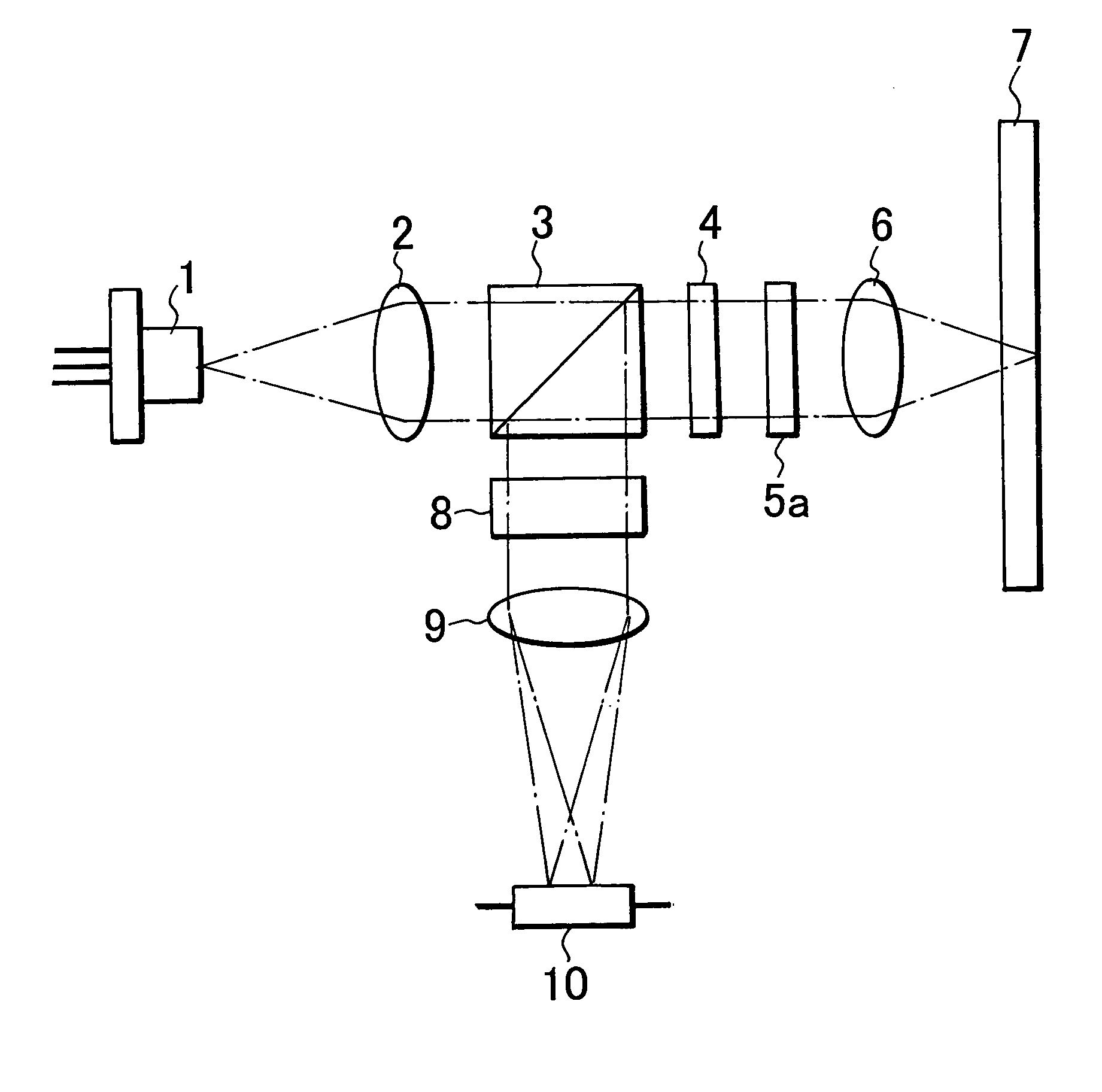
[0045]FIG. 1 is a schematic diagram of optical head device according to the invention. Referring to FIG. 1, light emitted from a semiconductor laser 1, which is the light source of the embodiment, is collimated by a collimator lens 2. Then, it enters a polarization beam splitter 3 as P-polarized light and transmitted through it substantially by 100%. Subsequently, it is transmitted through a ¼ wave plate 4 and converted into circularly polarized light from linearly polarized light before it is transmitted through a birefringence correcting element 5a and converged on a disk 7, which is an optical recording medium, by means of an objective lens 6. Light reflected by the disk 7 is transmitted through the objective lens 6, the birefringence correcting element 5a and the ¼ wave plate 4 in the opposite direction, where it is converted into linearly polarized light with a direction of polarization orthogonal relative to the direction of polarization of forward-moving light from circularly...

fifth embodiment

[0097]FIG. 12 is a graph illustrating the computationally determined relationship between the duty ratio of the lattice and the effective refractive index of the birefringence correcting element of optical head device according to the invention. The two mediums of this embodiment are air and quartz and hence n1=1 and n2=1.47. In FIG. 12, ● indicates the computationally determined values that are obtained for the effective refractive index n∥ relative to the polarized light component that is parallel with the lattice (TE-polarized light) and ◯ indicates the computationally determined values that are obtained for the effective refractive index n⊥ relative to the polarized light component that is perpendicular to the lattice (TM-polarized light). If Δn=n∥−n⊥, Δn shows the smallest value of 0 when q=0 and the largest value of 0.0887 when q=0.45.

[0098]FIGS. 13A through 13D are schematic cross sectional views of the birefringence correcting element 5e. The birefringence correcting element...


PUM


Abstract

In an optical head device, a birefringence correcting element 5a containing a material showing mono-axial refractive index anisotropy is located before an objective lens. The birefringence correcting element 5a is circumferentially divided into four regions by two straight lines passing through an optical axis and intersecting each other at right angle. Each of the four regions is radially divided into four sub-regions by three circles centered at the optical axis. The direction of optic axes of the sub-regions 11a to 14a and 11c to 14c is a direction of x-axis, while the direction of optic axes of the sub-regions 11b to 14b and 11d to 14d is a direction of y-axis. A phase difference of sub-regions between a polarized light component polarized in a direction parallel to the optic axis and another polarized light component polarized in a direction vertical to the optic axis increases in order of the sub-regions 11a to 11d, sub-regions 12a to 12d, sub-regions 13a to 13d and the sub-regions 14a to 14d.

Description

BACKGROUND OF THE INVENTION [0001] 1. Field of the Invention [0002] This invention relates to an optical head device and an optical information recording / reproduction apparatus adapted to show excellent recording / reproduction characteristics by correcting the influence of birefringence of the protection layer of the optical recording medium on incident light or reflected light. [0003] 2. Description of Related Art [0004]FIG. 15A of the accompanying drawings schematically illustrates a known popular optical head device. Incident light from a semiconductor laser 1, which is a light source, is collimated by a collimator lens 2 and enters a polarization beam splitter 3 as P-polarized light so as to be transmitted through it substantially by 100%. Then, it is transmitted through a ¼ wave plate 4 and converted into circularly polarized light from linearly polarized light before it is converged on a disk 7, which is an optical recording medium, by means of an objective lens 6. Light reflec...

Claims


Application Information

Patent Timeline
IPC IPC(8): G02B5/30G02F1/01G02F1/1333G11B7/00G11B7/135
CPCG02F1/01G02F2203/18G11B7/1369G11B7/1367G11B7/1365
Inventor KATAYAMA, RYUICHI
Owner NEC CORP
Why Eureka
Try Eureka