Small magnetic disk cartridge

a magnetic disk and cartridge technology, applied in the field of small magnetic disk cartridges, can solve the problems of slow recording speed, high cost of memory hard disk type, and relatively expensive memory type of semiconductors, and achieve the effect of convenient operation of mounting the magnetic disk on the disk mounting hub, convenient rotation, and improved dimensional accuracy of the disk drive assembly

Inactive Publication Date: 2005-01-04
FUJIFILM CORP +1
View PDF2 Cites 0 Cited by
  • Summary
  • Abstract
  • Description
  • Claims
  • Application Information

AI Technical Summary

Benefits of technology

According to the magnetic disk cartridge of the present invention constructed as described above, the small area of the center portion of the magnetic disk is mounted at one point on the disk-mounting hub. Therefore, wrinkles and distortions are less liable to occur around the center portion of the magnetic disk. As a result, the flatness of the magnetic disk can be maintained during rotation, and a magnetic head can touch the magnetic dis

Problems solved by technology

However, the semiconductor memory type is relatively expensive.
Although there are known some hard disks that can store 340 megabytes (MB) of data or 1 gigabytes (GB) of data, the hard disk type of memory is similarly expensive.
However, optical disks have the disadvantage that the recording speed is slow, because the writing time is time-consuming.
However, the recording capacity is as small as 40 MB and insufficient to store data photographed by a camera.
In addition, the size is not suitable for digital cameras.
However, digital cameras are restricted in use, because recording media are restricted in cost and recording capacity, as described above.
For instance, since recording media are very expensive, o

Method used


Image

  • Small magnetic disk cartridge
  • Small magnetic disk cartridge
  • Small magnetic disk cartridge

Examples


first embodiment

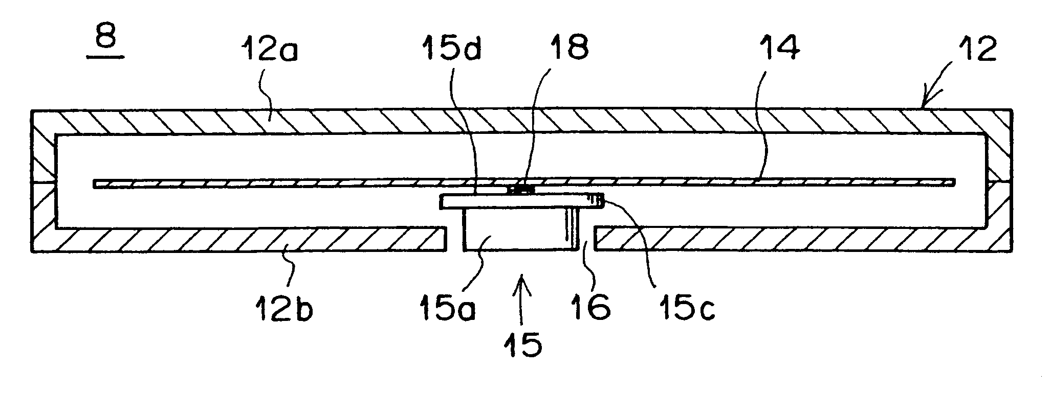
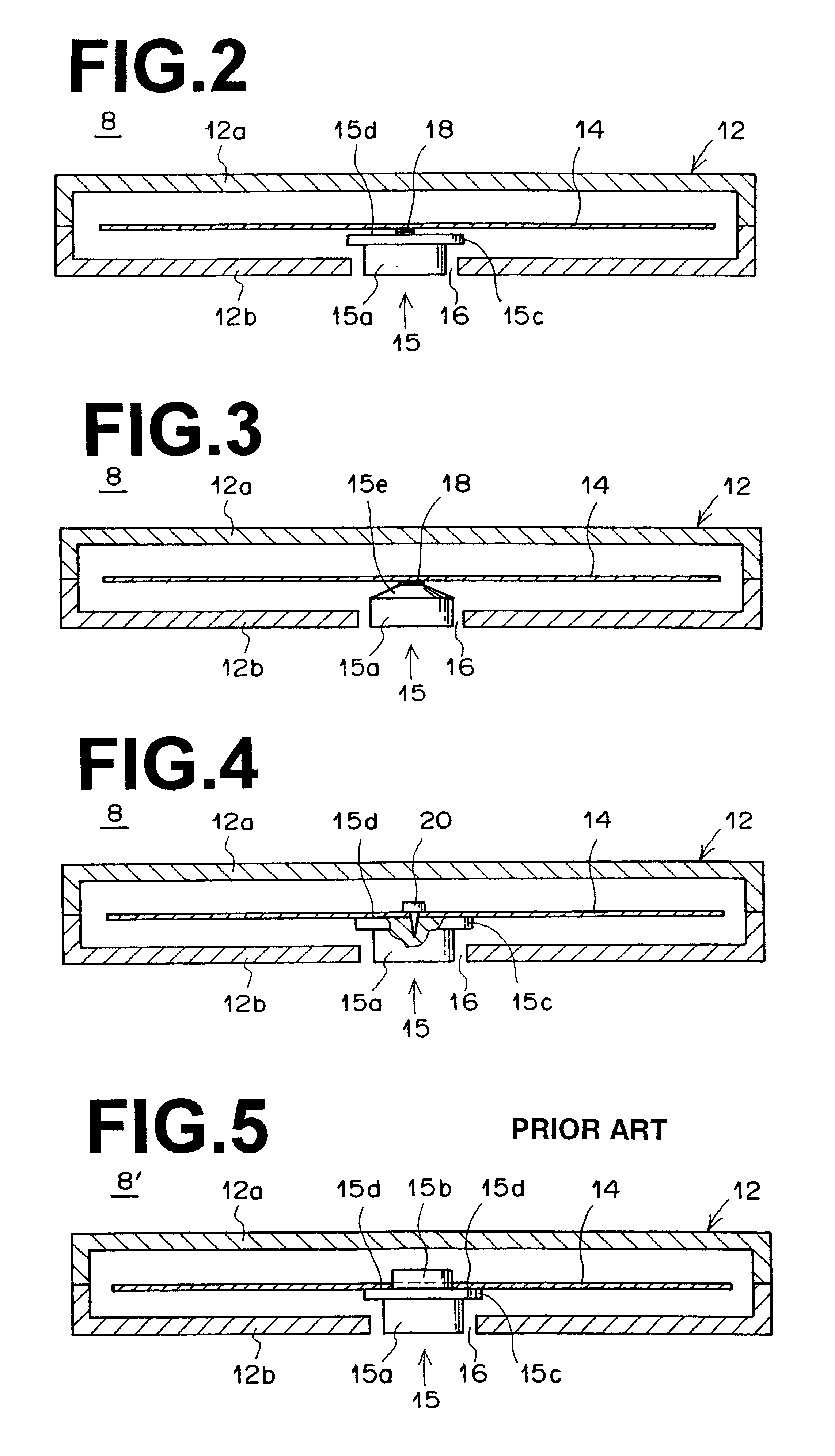
Referring now to FIG. 2, there is shown a small magnetic disk cartridge 8 constructed in accordance with the present invention. The magnetic disk cartridge 8 has a flat housing 12 in which a magnetic disk 14 is rotatably supported. This magnetic disk 14 has no center hole and is constructed of a material that has a recording capacity of 200 MB or larger. For example, the magnetic disk 14 is constructed of the above-described magnetic recording medium that has a magnetic layer with a high recording density containing barium ferrite powder.

A disk-mounting hub 15 has a shaft portion 15a which is magnetically chucked by the spindle of the above-described disk drive 6, and a flange portion 15c which has a flat top face 15a. The lower shell 12b of the housing 12 has a spindle hole 16 to expose the disk-mounting hub 15. The center portion of the under side of the magnetic disk 14 is mounted at one point on the top face 15d of the disk-mounting hub 15 by an adhesive agent 18. The diameter o...

second embodiment

(1) The small area of the center portion of the magnetic disk 14 is mounted at one point on the disk-mounting hub 15. Therefore, wrinkles and distortions are less liable to occur around the center portion of the magnetic disk 14. As a result, the flatness of the magnetic disk 14 is maintained during rotation, and a stable head touch can be assured. (2) In the case where the magnetic disk 14 is mounted on the top face of the truncated cone 15e of the disk-mounting hub 15, as in the second embodiment shown in FIG. 3, a recess in which the flexible magnetic disk 14 can move downward is present between the flexible magnetic disk 14 and the truncated cone 15e. This recess can absorb the dimensional accuracy of the assembly of the disk drive 6 and the dimensional accuracy of the assembly of the magnetic disk cartridge 8. (3) The operation of mounting the magnetic disk 14 on the disk-mounting hub 15 is easier than the conventional operation of annularly mounting the magnetic disk cartridge...


PUM


Abstract

A small magnetic disk cartridge for use in a card disk drive to be loaded in electronic equipment. The magnetic disk cartridge comprises a housing, a disk-mounting hub rotatable within the housing by a spindle provided in the disk drive, and a flexible magnetic disk mounted at one point on the disk-mounting hub.

Description

BACKGROUND OF THE INVENTION1. Field of the InventionThe present invention relates to a small magnetic disk cartridge, and particularly to a small magnetic disk cartridge that can be exchangeably loaded in a card disk drive that can be loaded in the card slot of electronic equipment such as a digital still camera, a digital video camera, a laptop personal computer, etc.2. Description of the Related ArtTo record or reproduce information, a wide variety of recording media are removably loaded in the card slot of electronic equipment such as a digital still camera, a digital video camera, a laptop personal computer (PC), etc. Such recording media that are in practical use are a semiconductor memory type, a hard disk type, an optical disk type, a magnetic disk type (e.g., a floppy disk type), etc.Among these recording media, the semiconductor memory type is most widely used, because it is easy to handle and has a relatively large recording capacity. However, the semiconductor memory type...

Claims


Application Information

Patent Timeline
IPC IPC(8): G11B23/03G11B23/00G11B23/033
CPCG11B23/0317G11B23/0305
Inventor ENDO, YASUSHI
Owner FUJIFILM CORP
Why Eureka
Try Eureka