Rotatable head for forming spiral extrusions

a technology of spiral extrusion and rotatable head, which is applied in the field of cross-line extrusion head and extrusion cross-head, can solve the problems of difficult to provide a rotatable seal, requiring shutdown of the process to clean and restart, and having a rotatable die. achieve the effect of high seal for

Inactive Publication Date: 2005-11-24
CANGEN HLDG
View PDF5 Cites 35 Cited by
  • Summary
  • Abstract
  • Description
  • Claims
  • Application Information

AI Technical Summary

Benefits of technology

[0014] To create high seal force of the rotating die against the wear plate, the die is dynamically loaded axially against the plate by a Belleville washer compressed within the sub-assembly. The bearings are disposed behind the drive flange of the sub-assembly hub such that they are protected from contamination by any polymer that may leak from the interface between the wear plate and the rotatable die. Further, progressive relaxation of the Belleville washer assures a continuing load on the wear surface, permitting extended extrusion runs uninterrupted by loss of seal pressure.

Problems solved by technology

Several problems exist in prior art extrusion heads having rotatable dies.
First, it has been found to be difficult to provide a rotatable seal to prevent leakage of molten polymer from the head between the stationary and rotating components.
Typically, such leakage causes continuous polymer buildup on the outside of the head, eventually requiring shutdown of the process to clean and restart.
Second, polymer may leak into the bearings, causing failure of the head.

Method used


Image

  • Rotatable head for forming spiral extrusions
  • Rotatable head for forming spiral extrusions
  • Rotatable head for forming spiral extrusions

Examples


Embodiment Construction

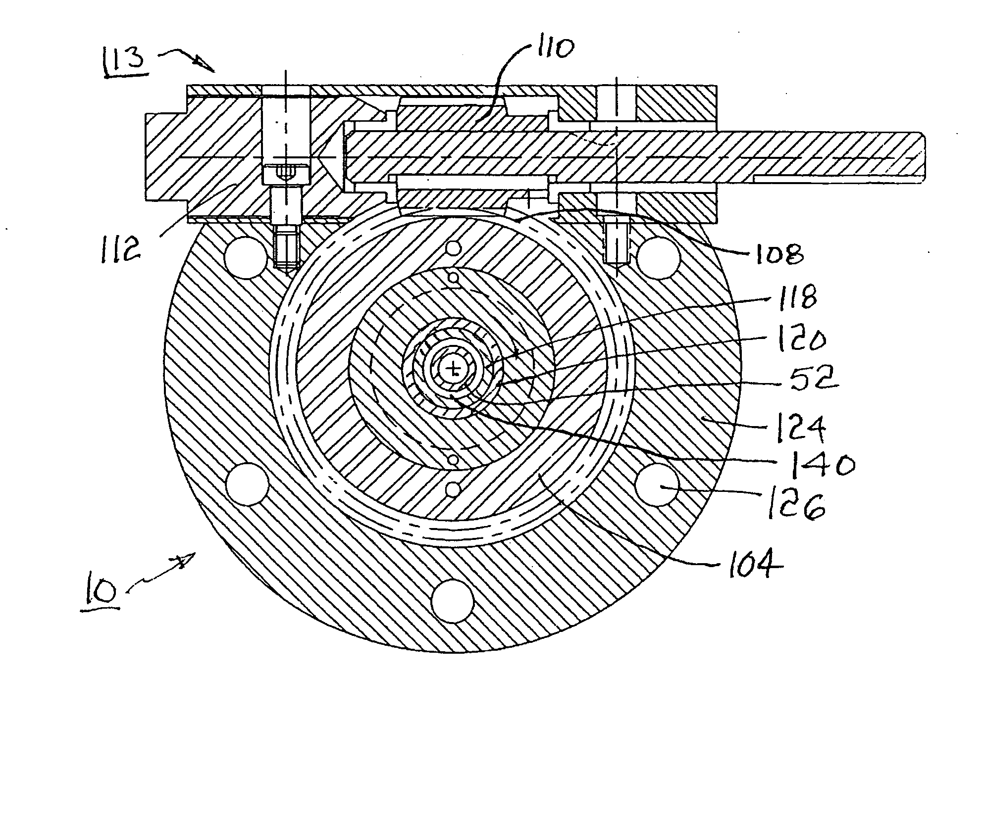
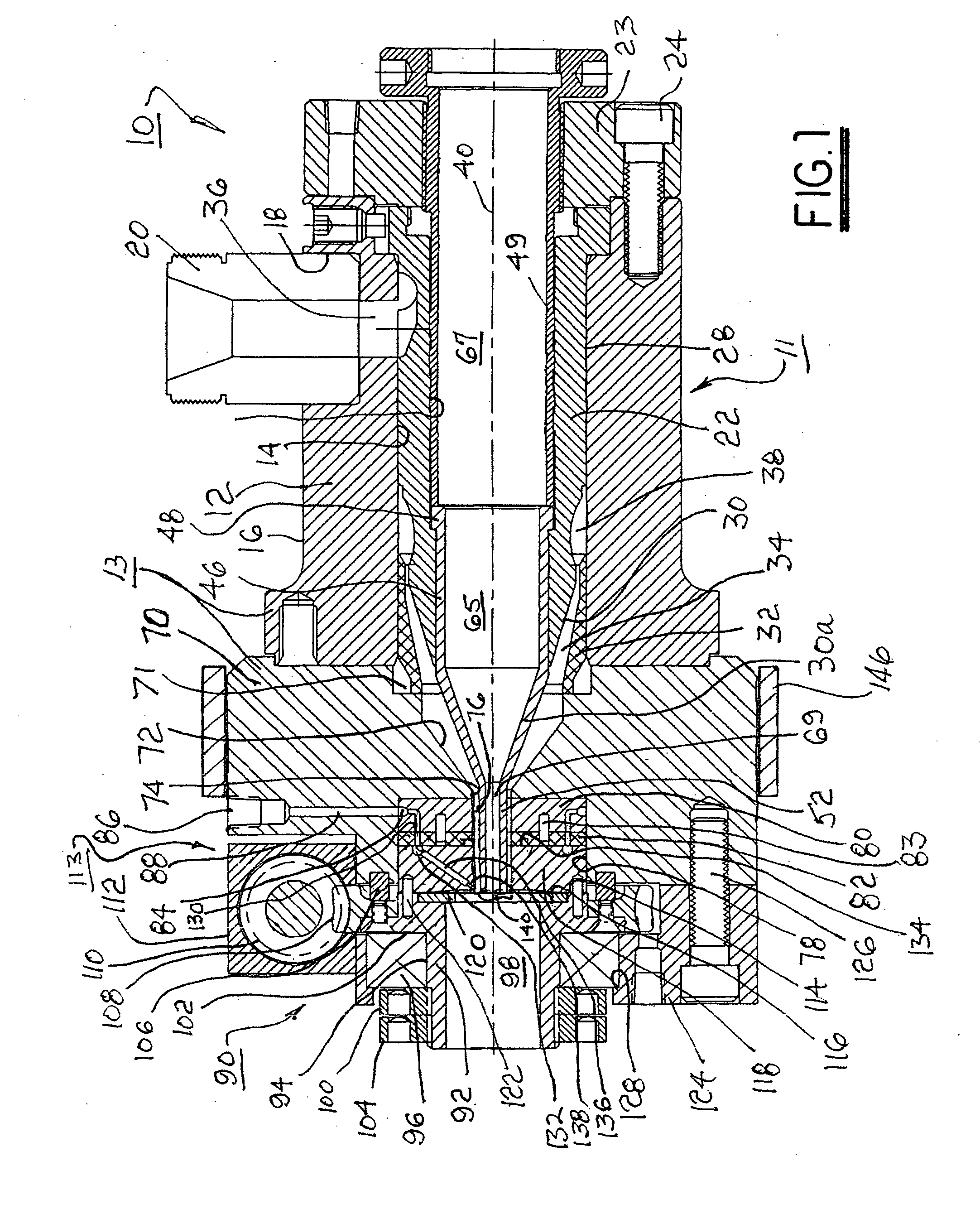
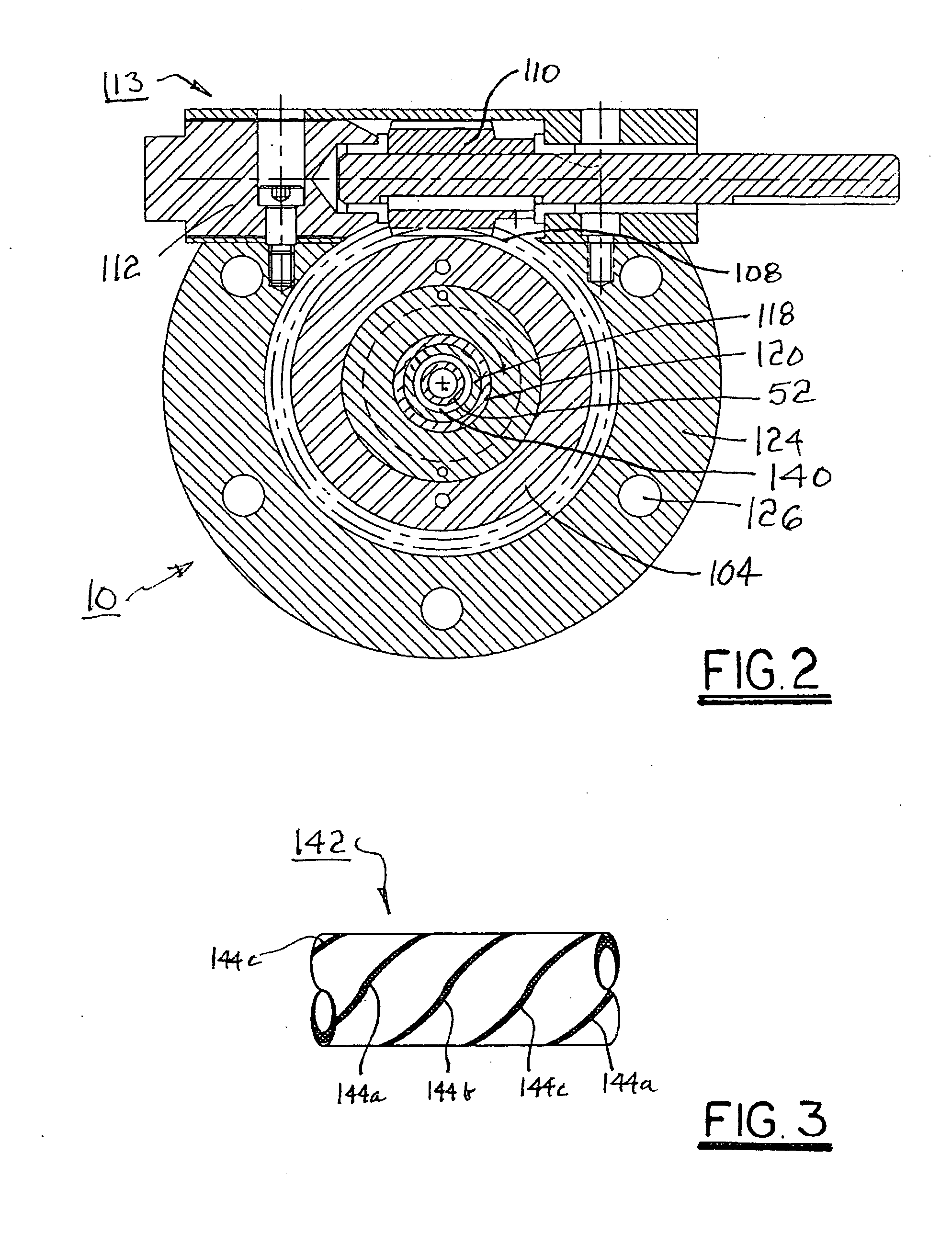
[0020] Referring to FIGS. 1 and 2, there is shown an exemplary embodiment 10 of an improved extrusion crosshead assembly in accordance with the invention. Embodiment 10 comprises a prior art front end portion for providing a flow of primary polymer to be extruded, and a novel rotatable die sub-assembly for providing one or more stripes of a secondary polymer in the primary polymer extrusion.

[0021] A first body section 12 of a body element 13 is substantially cylindrical on an inner surface 14 and outer surface 16 thereof. A radial bore 18 therein is receivable of supply means 20 for providing a primary molten polymer to assembly 10 in use thereof. A mandrel 22 is disposed within body section 12 and secured therein via ring 23 and bolts 24. Mandrel 22 includes a cylindrical outer surface portion 28 that is close-fitting to inner body surface 14 and a tapered portion 30. A conically tapered insert 32 cooperates with tapered portion 30 to define a decreasive annular flow space 34. A r...


PUM

PropertyMeasurementUnit
shapeaaaaaaaaaa
frictionaaaaaaaaaa
cylindrical shapeaaaaaaaaaa

Abstract

A polymer extrusion crosshead assembly for forming a spirally-striped extrusion. The assembly includes conventional components for admitting, turning, and accelerating primary molten polymer toward a novel rotating die sub-assembly. A body element includes an axial counterbore for receiving a manifold supply block in communication with a source of secondary striping polymer. A wear plate is attached to the manifold block. The die sub-assembly includes a striping die having an annular passage for conveying the primary polymer to form an extruded tube or a core material coating. The die is loaded against the wear plate by a Belleville washer. The die includes one or more striping nozzles in communication with the manifold block for injecting secondary striping polymer into the annular stream of primary polymer flowing through the die, creating a longitudinal stripe of striping polymer. Rotating the die while extruding both polymers yields a helically striped (spiral) extrusion.

Description

TECHNICAL FIELD [0001] The present invention relates to apparatus for extrusion forming of molten polymer material; more particularly, to crossline extrusion heads for continuous extrusion coating of hollow or solid shapes; and most particularly, to an extrusion crosshead having a rotatable secondary die for forming a spiral stripe in a cylindrical extrusion. BACKGROUND OF THE INVENTION [0002] Extrusion heads for continuous extrusion forming of continuous plastic elements having specific cross-sectional shapes are well known. Such extruded elements may include, for example, pipes, rods, moldings, tubings, and the like. [0003] In a typical prior art extrusion system, solid pellets of the thermoplastic material to be used are fed into a progressive-screw extruder wherein the pellets are liquefied under high pressure and are injected into an extrusion head. Such injection may be made axially of the extrusion head, known in the art as “inline,” or at an angle, typically 90°, to the axis...

Claims


Application Information

Patent Timeline
Patent Type & Authority Applications(United States)
IPC IPC(8): B29C48/06B29C48/07B29C48/09B29C48/33B29C48/34B65D1/00
CPCB29C47/0023B29C47/064Y10T428/2913B29C47/28B29C47/24B29C48/09B29C48/19B29C48/20B29C48/33B29C48/34B29C48/131B29C48/07B29C48/06
Inventor ANAND, PREMGIARDINA, JOHN C.
Owner CANGEN HLDG
Why Eureka
Try Eureka