
Nanoparticulate anionic clays

a technology of anionic clay and nanoparticulate, which is applied in the direction of colloidal chemistry, physical/chemical process catalysts, other chemical processes, etc., can solve the problems of not being able to determine the size and colloidal stability of the resulting product, not being able to carry out and produce products, and not being able to determine the particle size and colloidal stability of the resultant produ

Inactive Publication Date: 2005-11-24
EASTMAN KODAK CO
View PDF7 Cites 7 Cited by
  • Summary
  • Abstract
  • Description
  • Claims
  • Application Information

AI Technical Summary

Benefits of technology

The invention is about a new type of clay that can be used to make stable colloidal dispersions in liquids. This clay has the formula (M2+1-xM3+x(OH)2x+(x / n)An−.yH2O) or (M1+M3+2(OH)6)1+(1 / n)An−.yH2O. The clay is made up of particles with a small size, and it can be dispersed in liquid without clumping together. The invention also describes a method for making this clay by mixing metal salt solutions and a base in a high-speed mixing process. The technical effect of this invention is the creation of a new material that can be used to create stable colloidal dispersions in liquids, which could have various applications in different fields.

Problems solved by technology

The hydrothermal methods are not commonly used since they are generally more difficult to carry out and produce products having a large particle size (typically greater than 1-2 microns).
The reconstruction method is useful for carrying out ion-exchange reactions of hydrotalcite, but is not used to prepare pristine layered double hydroxides.
However, the particles size and colloidal stability of the resulting product are not determined, and no evidence is provided for composites having nanoscale dimensions.
The surface modification methods employed further are difficult and expensive to perform, and may disrupt the ability of the layered materials to act as chemical delivery agents.

Method used


Image

  • Nanoparticulate anionic clays

Examples


examples

Measurement of Particle Size

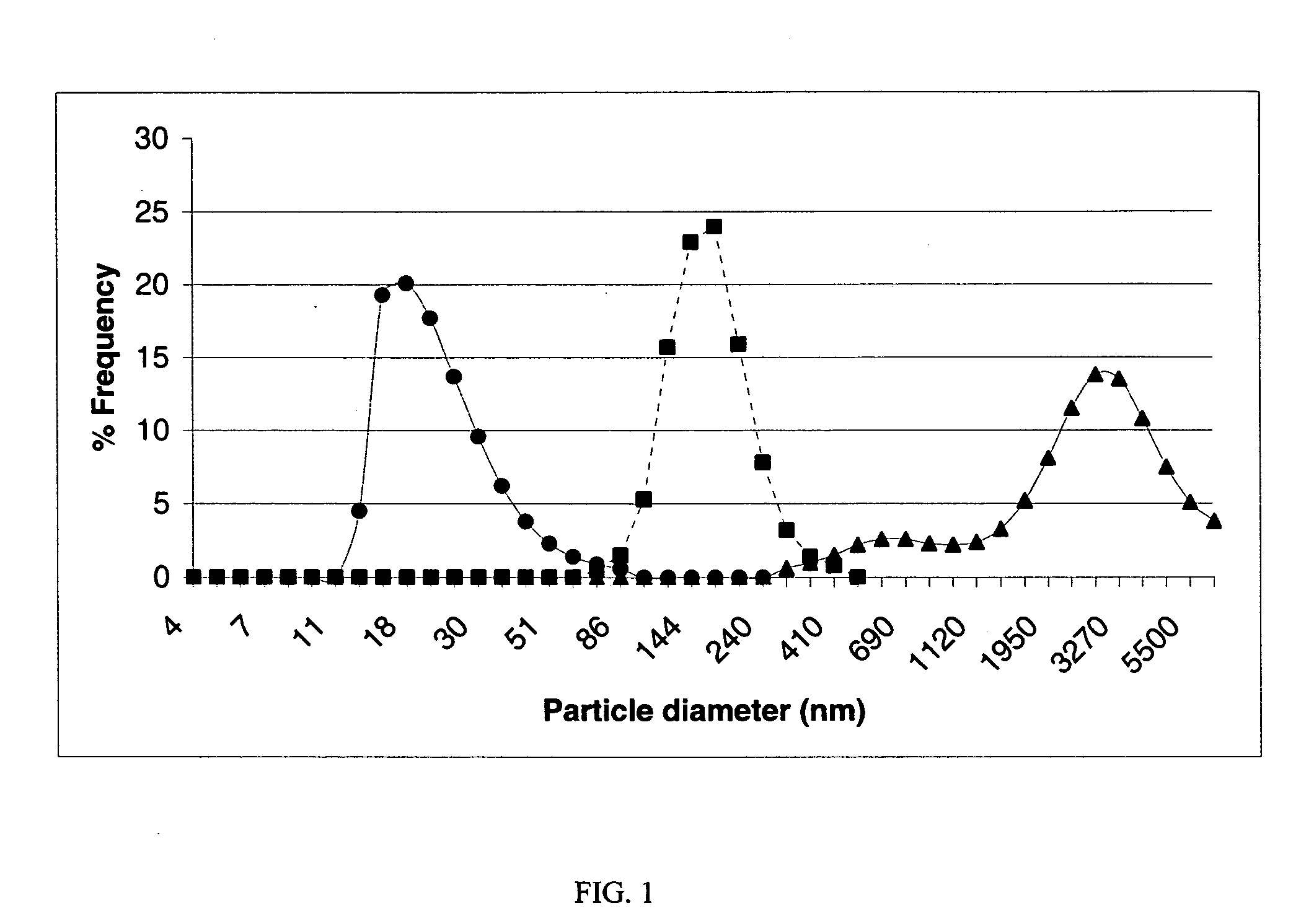
[0021] The volume-weighted, mean particle size diameters of anionic clay dispersions obtained in the following examples were measured by a dynamic light scattering method using a MICROTRAC® Ultrafine Particle Analyzer (UPA) Model 150 from Leeds & Northrop. The analysis provides percentile data that show the percentage of the volume of the particles that is smaller than the indicated size. The 50 percentile is known as the median diameter, which is referred herein as median particle size. The volume-weighted mean particle size diameter is calculated from the area distribution of the particle size as described in the MICROTRAC® Ultrafine Particle Analyzer (UPA) Model 150 manual. The standard deviation describes the width of the particle size distribution. The smaller the standard deviation the narrower the width of the distribution.

examples 1-3

Preparation of Nanoparticulate Anionic Clays, Materials and Methods

[0022] MgCl2:6H2O and AlCl3:6H2O and NaOH were purchased from Aldrich Chemical Company. Solutions were prepared using pure distilled water. A highly efficient prop-like mixing apparatus of the type described in Research Disclosure, Vol. 382, February 1996, Item 38213, was employed to prepare nanoparticulate colloids. Solutions were introduced into a zone of high shear mixing via calibrated peristaltic pumps at known flow rates. The mixing efficiencies and flow rates were varied to obtain stable nanoparticle colloidal dispersions. The mixing efficiency of the apparatus is described by the turnover rate, where the turnover rate=(stir rate(rev / min)×turnover volume (ml / rev)) divided by the aqueous volume. The mixing efficiency typically was kept constant for each example and was about 25 turnovers / min, or 0.4 turnovers / sec.

example 1

[0023] Into a 1.0 L vessel containing 200 ml of distilled water which was stirred with a prop-like stirrer at a rate of 2000 rpm was simultaneously added, 100.0 ml of a 1.0 M MgCl2:6H2O solution at 10 ml per minute for 10 minutes; 100.0 ml of a 0.5 M AlCl3:6H2O solution at 10 ml per minute for 10 minutes; and a 2.5 M NaOH solution at a rate sufficient to keep the pH of the reaction mixture between 8.5-9.0. The addition rate of 2.5 NaOH varied slightly between about 11 and 12 ml / min. After the addition was completed, the dispersion was then washed free of salt by dialfiltration, until the ionic conductivity of the dispersion was less than about 0.2 mS. The resulting dispersion had a mean particle size diameter of 134 nm with a standard deviation of 39 nm, and did not settle after standing three weeks indicating that the dispersion was a stable colloid. The percent solids of the final dispersion was 3.5% by weight. The particle size distribution parameters are given in Table 1. The pa...


PUM

PropertyMeasurementUnit
particle size diameteraaaaaaaaaa

Abstract

A composition of matter comprising anionic clay having the general formula [M2+1-xM3+x(OH)2]x+(x / n)An−.yH2O  (I) or [M1+M3+2(OH)6]1+(1 / n)An−.yH2O;  (II) where M1+ is a mono-valent metal; M2+ is a divalent metal; and M3+ is a trivalent metal; A is an inorganic or organic anion, chosen such that the rule of charge neutrality is obeyed; n is an integer; x is any rational number between 0 and 1; and y is any rational number between 0 and 10; where the anionic clay is in the form of particles having a volume weighted mean particle size diameter of less than 500 nm. Stable colloidal dispersions comprise such anionic clay particles having a volume weighted mean particle size diameter of less than 500 nm dispersed in a liquid medium. Method for preparing such stable colloidal dispersion of anionic clay particles comprises simultaneously bringing together salt solutions of M2+ and M3+ metals, or of M1+ and M3+ metals, and a base in a high shear mixing zone within a liquid dispersion medium in a particle precipitation vessel, and precipitating anionic clay particles having a volume weighted mean particle size diameter of less than 500 nm.

Description

FIELD OF THE INVENTION [0001] The present invention relates to nanoparticulate size anionic clay compositions, stable colloidal dispersions of nanoparticulate size anionic clay particles, and methods of preparing stable colloidal dispersions of nanoparticulate size anionic clay particles. BACKGROUND OF THE INVENTION [0002] Nanoparticulate materials have received much attention recently as a result of their unique physical properties and applications in a variety of devices and products. Nanoparticulate silica and alumina colloids have been known for many years and have many uses in industrial, medical and consumer products. Much effort has been given to the development of novel nanoparticulates, and to the study of their physical properties. A nanoparticle has dimensions on the order of a molecular scale, typically between about 1-100 nm, or 10−9 to 10−7 meters. [0003] Layered compounds are a unique class of materials that have strong chemical bonding in two-dimensions but only weak...

Claims


Application Information

Patent Timeline
Patent Type & Authority Applications(United States)
IPC IPC(8): C01F7/785B01F3/12B01JB01J21/16
CPCB82Y30/00C01F7/005C01P2002/22C01P2004/51Y10S977/786Y10S977/90Y10S977/81Y10S516/927Y10S977/773C01F7/785
Inventor BRINGLEY, JOSEPH F.MORRIS, CRAIG A.
Owner EASTMAN KODAK CO
Learn More