Infusion device and method

a technology of infusion device and needle, which is applied in the field of medical devices, can solve the problems of urging the needle undesiredly into and out of the tube, difficulty in restoring blood flow to the heart muscle, and difficulty in achieving the effect of less cutting and less sharpness

Inactive Publication Date: 2005-11-24
BOSTON SCI SCIMED INC
View PDF50 Cites 29 Cited by
  • Summary
  • Abstract
  • Description
  • Claims
  • Application Information

AI Technical Summary

Benefits of technology

[0006] The present invention includes improved devices and methods for performing PMR procedures. One device allows for improved preparation of PMR catheters used to inject a drug or therapeutic substance into the heart wall. One such device includes a PMR device distal region or hood disposed within the neck of a vial for receiving the drug. The vial can be used to receive the drug while the drug is being flushed through the PMR device and needle to prepare the PMR device for use. One vial has a neck and shoulder region for receiving and retaining the distal region of a PMR injection device. A no-leak gasket defines one wall of an inner cavity within one such vial.
[0007] The vial is preferably formed of a transparent or translucent material for observing the injection of the drug into the vial. In one embodiment, the vial cavity includes a drug-neutralizing agent. The agent allows the drug to be neutralized after receiving the drug. A neutralizing agent can provide improved safety, should the integrity of the vial be breached. The drug-neutralizing vial allows a biologically active drug to be flushed through the catheter with the vial being disposed of in a normal waste stream such as a wastebasket, rather than requiring special handling.
[0008] One set of devices provides improved needle attachment to drug delivery tubes. One improved drug delivery tube has an outer tube defining a lumen therein. A needle may be disposed within the distal end of the tube. The needle can have a distal, sharp tube region for insertion into the heart wall, as a well as a wider, more proximal region having outward protrusions for engaging or biting into the drug delivery tube inner wall. One device has a wide flange for abutting the drug delivery tube distal end, thereby limiting the proximal travel of the needle into the drug delivery tube lumen. One drug delivery tube also has a bonding hole which can be used to inject an adhesive to further secure the needle within the drug delivery tube distal region. The improved securing of the needle to the drug delivery tube can act to prevent the needle from being distally pulled from the tube.
[0013] The present invention also includes a PMR device for allowing precise, variable depth needle penetration of the heart wall. One device includes at least one inner stop affixed to a rotatable inner needle. The device also can have one or more stops disposed inwardly from an outer tube, the outer tube having the inner needle rotatably disposed within. The inner needle can be longitudinally advanced until the inner stop abuts an outer stop, thereby inhibiting further distal movement of the inner needle. If greater penetration is desired, the inner shaft can be rotated, thereby swinging the inner stop clear of the first encountered outer stop, allowing the inner stop to proceed further distally until a subsequent outer stop is encountered. This aspect of the invention allows a single device to be used, yet provides multiple, preset, precise penetration depths. This may be of particular use where the thickness of the heart wall varies over different regions of the heart chamber wall.
[0014] Yet another aspect of the invention provides for injection of drug and contrast media into the heart wall. Injection of contrast media near the injection site of a drug allows the treating physician to visualize under fluoroscopy which areas of the heart wall have been treated and which have not yet been treated. One device provides a contrast media injection needle disposed side-by-side with a drug delivery needle. One embodiment allows the two side-by-side needles to be retracted and advanced together. The needles can be distally straight, arcuate, or one arcuate and one straight. Another embodiment provides a drug and contrast media injection device having a pair of needles, one being coaxially disposed within the other. The innermost needle can be used to inject drug deep into the heart tissue, while the more outer, coaxially disposed needle may be used to inject contrast media to the heart wall, thereby marking the site of treatment. One embodiment utilizes a sharp, cutting end to inject contrast media. Another embodiment uses a less sharp, less cutting end, for injecting a contrast media into the heart wall tissue using pressure, rather than cutting.

Problems solved by technology

For example, in some patients, the number of lesions in coronary vessels is so great or the location so remote in the patient vasculature that restoring blood flow to the heart muscle is difficult.
This preparation can be awkward and may leave a container of biologically active material which may require further processing.
In particular, forces may act upon the needle during both the advancement and retraction of the needle within the heart wall, urging the needle undesirably both into and out of the tube.
This may presently be difficult to visualize under fluoroscopy as current marking systems for shafts may make interpretation of the catheter distal region orientation somewhat ambiguous.

Method used


Image

  • Infusion device and method
  • Infusion device and method
  • Infusion device and method

Examples


Embodiment Construction

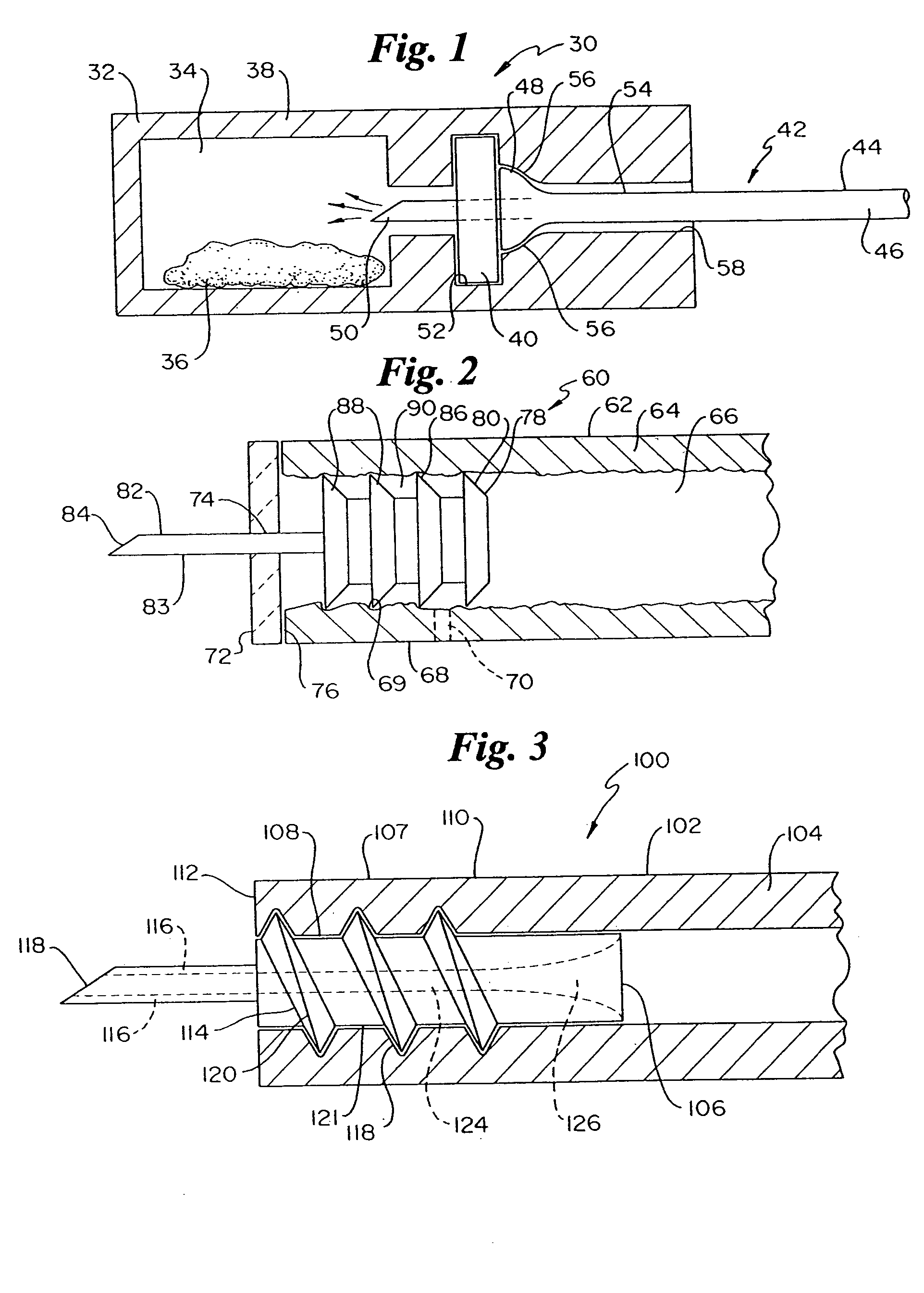
[0029]FIG. 1 illustrates a myocardial revascularization drug delivery preparation assembly 30 including a drug receiving vial 32 and a drug delivery catheter 42 inserted into vial 32. Drug delivery catheter 42 includes a tube 44 having a lumen 46 therethrough. Catheter 42 includes a distal portion 54 having an injection device or needle 50 in fluid communication with lumen 46. Catheter 42 further includes a distal hood 48, illustrated in an expanded state. Drug injection needle 50 is illustrated penetrating through a self-sealing, no-leak gasket 40. Gasket 40 can be disposed within vial 32 in an annular seat 52, as shown.

[0030] Drug receiving vial 32 includes a wall 38, which is preferably formed of a transparent or translucent material, allowing both an expelled drug and catheter needle to be viewed through the vial wall. Vial 32 includes a cavity 34 having a drug-neutralizing agent 36 disposed within cavity 34. Vial 32 includes a neck region 58 for receiving catheter distal porti...


PUM


Abstract

Devices and methods for performing improved percutaneous myocardial revascularization (PMR) procedures. One device includes a preassembled PMR drug delivery catheter and a drug neutralizing vial. The vial assembly allows prepping the PMR catheter by flushing drug through distal needle, and into a vial cavity where the drug is neutralized by a neutralizing agent. One set of devices includes needles having protrusions secured to the distal regions of drug delivery tubes. One needle has outward protruding barbs engaging the inner tube wall while another needle has outward threads which can screw into the tube inner wall. Radiopaque marker bands are also included in the present invention which are asymmetrically distributed on the catheter shaft, allowing a treating physician to determine under fluoroscopy whether the catheter distal region is pointed away or toward the treating physician, as well as determining whether the catheter distal region is rotated toward or away from the treating physician. PMR devices include catheters having dual injection needles, for both injecting a drug into the heart wall and a radiopaque contrast media to mark the already treated sites. One PMR injection device has multiple stops for allowing controlled, variable needle depth penetration with a single distal needle tip.

Description

RELATED CASES [0001] The present application is a continuation of U.S. application Ser. No. 10 / 621,378, which was filed on Jul. 18, 2003, was entitled Infusion Devices and Method and is now U.S. Pat. No. ______. The '378 application is itself a continuation of U.S. Pat. No. 6,616,626, which was filed on Dec. 21, 2000 and shares the same name.FIELD OF THE INVENTION [0002] The present invention is related generally to medical devices. More specifically, the present invention is related to devices and methods associated with delivery of genes or therapeutic substances. BACKGROUND OF THE INVENTION [0003] A number of techniques are available for treating heart disease and diseases of other organs percutaneously. Examples of such techniques include delivery of genes and therapeutic substances, including the delivery of genes and therapeutic substances for percutaneous myocardial revascularization (PMR). This procedure is performed to increase blood perfusion through the myocardium of a pa...

Claims


Application Information

Patent Timeline
Patent Type & Authority Applications(United States)
IPC IPC(8): A61J1/00A61J1/14A61M5/46A61M25/00A61M25/01A61M25/06A61M25/098
CPCA61J1/1406A61M5/46A61M25/0068A61M25/0074A61M25/0084A61M25/0108A61M2210/125A61M2025/0008A61M2025/0081A61M2025/0085A61M2025/0086A61M2025/0091A61M2205/19A61M25/0662
Inventor CRANK, JUSTINLARSON, SCOTTMICKLEY, TIMOTHY J.
Owner BOSTON SCI SCIMED INC
Why Eureka
Try Eureka