Gas turbine control apparatus and gas turbine system using the same

a control apparatus and gas turbine technology, applied in mechanical equipment, lighting and heating equipment, machines/engines, etc., can solve the problems of different actual flow rates from those at the design of gas turbines, reduced combustion stability, and caused combustion oscillations, so as to improve the combustion stability of gas turbines

Inactive Publication Date: 2005-12-01
MITSUBISHI HITACHIPOWER SYST LTD
View PDF0 Cites 24 Cited by
  • Summary
  • Abstract
  • Description
  • Claims
  • Application Information

AI Technical Summary

Benefits of technology

[0006] Therefore, an object of the present invention to provide a gas turbine control apparatus and a gas turbine system, in which combustion oscillations in a gas turbine can be suppressed and combustion stability of the gas turbine can be improved.
[0007] Another object of the present invention is to provide a gas turbine control apparatus and a gas turbine system in which an air pollution level of the combustion in the gas turbine can be reduced.
[0008] Still another object of the present invention is to provide a gas turbine control apparatus and a gas turbine system, in which frequencies of combustion oscillations in a gas turbine can be analyzed and combustion oscillations can be properly suppressed in accordance with the result of the analysis.

Problems solved by technology

However, there is a possibility that actual flow rates are different from those at the design of the gas turbine or those on test running, because of degradation of a compressor and clogging of a filter.
At that time, the combustion stability can be reduced and combustion oscillations will be caused.
The combustion oscillations seriously obstruct the operation of gas turbine.
However, these works by turn raise the maintenance cost and reduce the operation rate of the gas turbine.

Method used


Image

  • Gas turbine control apparatus and gas turbine system using the same
  • Gas turbine control apparatus and gas turbine system using the same
  • Gas turbine control apparatus and gas turbine system using the same

Examples


first embodiment

[0064] Now, the gas turbine control apparatus according to the first embodiment of the present invention and the gas turbine system with the above gas turbine 2 of the present invention will be described below with reference to the attached drawings.

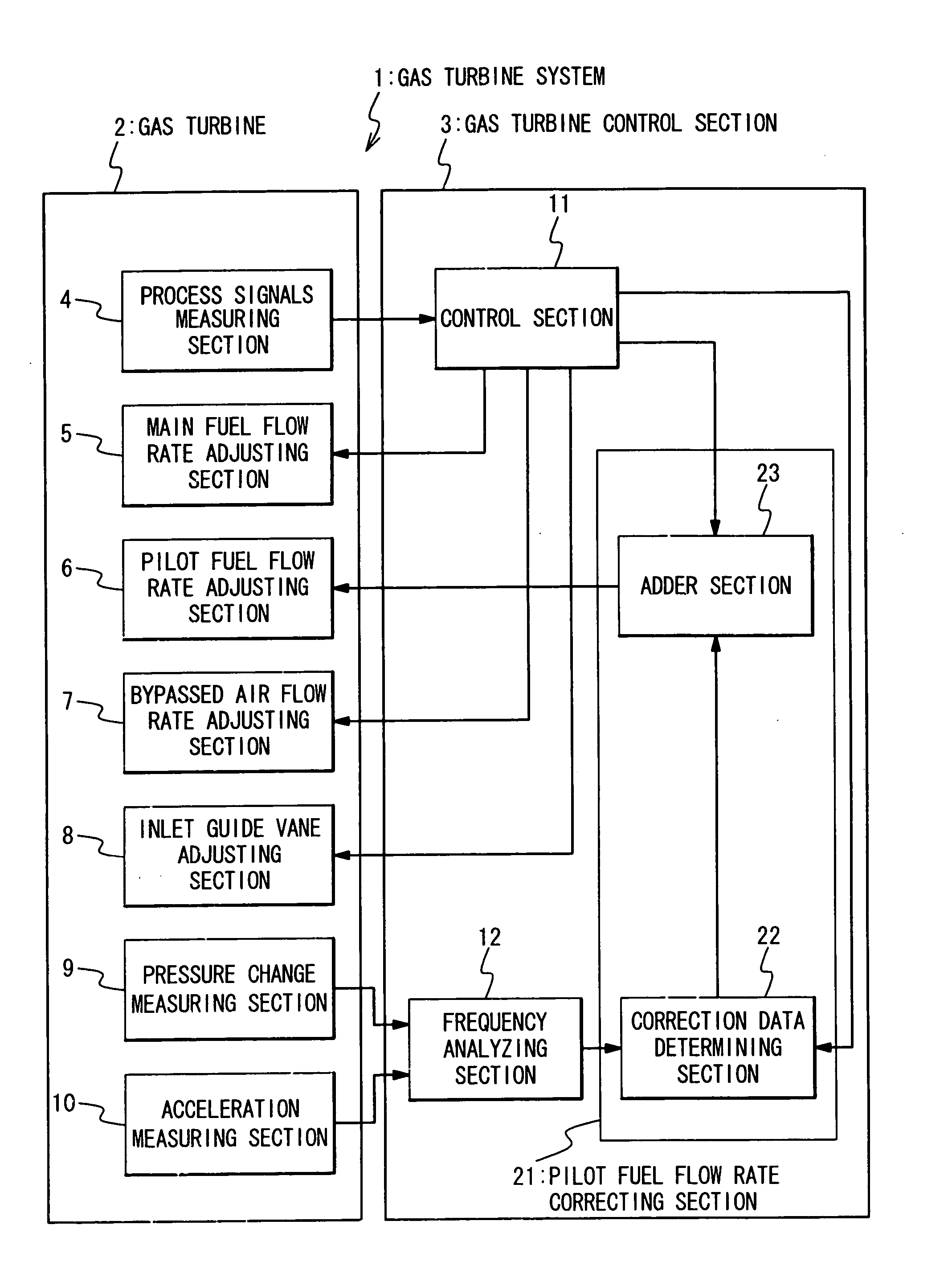
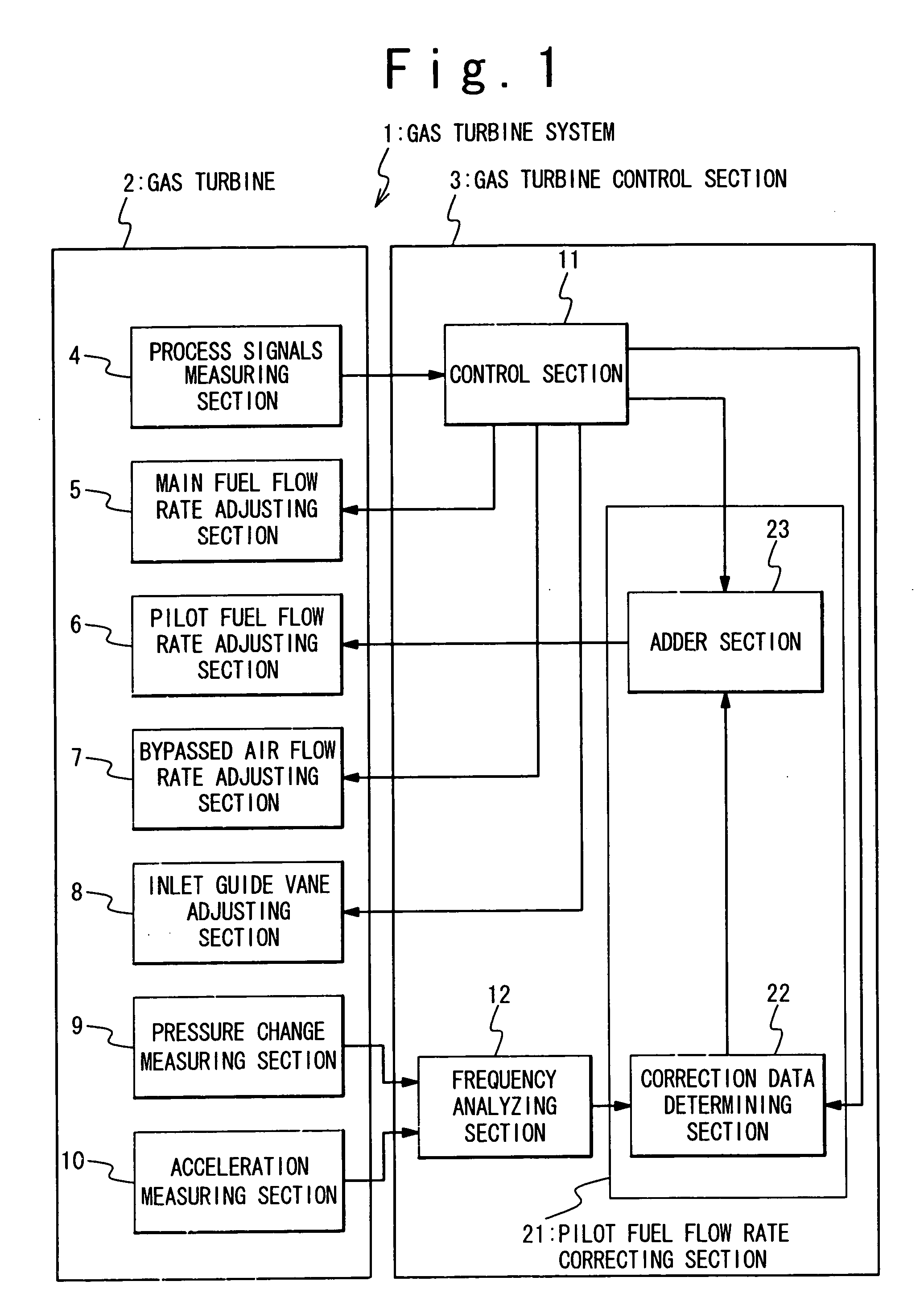
[0065]FIG. 1 is a block diagram showing the circuit structure of the gas turbine control apparatus of the present invention. The gas turbine system 1 is comprised of a gas turbine 2 and a gas turbine control section 3 as the gas turbine control apparatus of the present invention.

[0066] The gas turbine 2 is comprised of a process values measuring section 4, a main fuel flow rate adjusting section 5, a pilot fuel flow rate adjusting section 6, a bypassed air flow rate adjusting section 7, an inlet guide vane adjusting section 8, a pressure change measuring section 9 and an acceleration measuring section 10.

[0067] On the other hand, the gas turbine control section 3 is comprised of a control section 11, a frequency analyzing section 12 a...

embodiment 2

[0117] Now, gas turbine control apparatus for the gas turbine 2 and the gas turbine system using the control apparatus and the gas turbine 2 according to the second embodiment of the present invention will be described below with reference to the attached drawings.

[0118]FIG. 4 is a schematic block diagram showing the structure of the gas turbine control apparatus and the gas turbine system according to the second embodiment of the present invention. The gas turbine system 1 is comprised of the gas turbine 2 and the gas turbine control section 3 as the gas turbine control apparatus of the present invention.

[0119] The gas turbine 2 is comprised of the process values measuring section 4, the main fuel flow rate adjusting section 5, the pilot fuel flow rate adjusting section 6, the bypassed air flow rate adjusting section 7, the inlet guide vane adjusting section 8, the pressure change measuring section 9 and the acceleration measuring section 10.

[0120] On the other hand, the gas tur...

embodiment 3

[0146] Now, the gas turbine control apparatus for the gas turbine 2 and the gas turbine system containing the control apparatus according to the third embodiment of the present invention will be described below with reference to the attached drawings.

[0147]FIG. 5 is a schematic block diagram showing the structure of the gas turbine control apparatus and the gas turbine system according to the third embodiment of the present invention. The gas turbine system 1 is comprised of the gas turbine 2 and the gas turbine control section 3 as the gas turbine control apparatus of the present invention.

[0148] The gas turbine 2 is comprised of the process values measuring section 4, the main fuel flow rate adjusting section 5, the pilot fuel flow rate adjusting section 6, the bypassed air flow rate adjusting section 7, the inlet guide vane adjusting section 8, the pressure change measuring section 9 and the acceleration measuring section 10.

[0149] On the other hand, the gas turbine control se...


PUM


Abstract

In a gas turbine control apparatus, a frequency analyzing section frequency-analyzes at least one of pressure oscillation in combustors of a gas turbine and acceleration oscillation of each of the combustors and outputs a first frequency analysis result as the result of frequency analysis for a plurality of predetermined frequency bands. A control unit controls at least one of a first fuel flow rate of fuel and a first air flow rate of air based on the first frequency analysis result for the plurality of frequency bands. The fuel and the air are supplied to the gas turbine.

Description

BACKGROUND OF THE INVENTION [0001] 1. Field of the Invention [0002] The present invention relates to an apparatus for controlling a gas turbine and a system with such an apparatus. More particularly, the present invention relates to a control apparatus for controlling combustion oscillations and a system with such a control apparatus. [0003] 2. Description of the Related Art [0004] For a conventional gas turbine, flow rates of air and fuel respectively fed to a combustor are determined in advance based on the output power of an electric power generator, and temperature and humidity of ambient air, and the conventional gas turbine is operated by using the determined flow rates. However, there is a possibility that actual flow rates are different from those at the design of the gas turbine or those on test running, because of degradation of a compressor and clogging of a filter. At that time, the combustion stability can be reduced and combustion oscillations will be caused. The combu...

Claims


Application Information

Patent Timeline
Patent Type & Authority Applications(United States)
IPC IPC(8): F01D17/16F02C7/057F02C7/228F02C9/00F02C9/18F02C9/22F02C9/26F02C9/28F02C9/50F02C9/52F23N5/16F23R3/26F23R3/34
CPCF01D17/162F05D2270/14F02C9/18F02C9/22F02C9/263F02C9/28F02C9/50F02C9/52F05D2270/083F23N5/16F23N2041/20F23R3/26F23R2900/00013F23R2900/00014F05D2260/96F02C7/228F23N2241/20
Inventor NOMURA, MASUMITOYAMA, KOZO
Owner MITSUBISHI HITACHIPOWER SYST LTD
Why Eureka
Try Eureka