

Thermoelectric power generation system
a technology of power generation system and thermoelectric unit, which is applied in the direction of generator/motor, machine/engine, light and heating apparatus, etc., can solve the problems of deteriorating power generation efficiency of thermoelectric unit, insufficient cooling capacity, and inability to generate power, so as to increase the amount of power generated by thermoelectric unit
- Summary
- Abstract
- Description
- Claims
- Application Information
AI Technical Summary
Benefits of technology
Problems solved by technology
Method used
Image

Examples
first embodiment
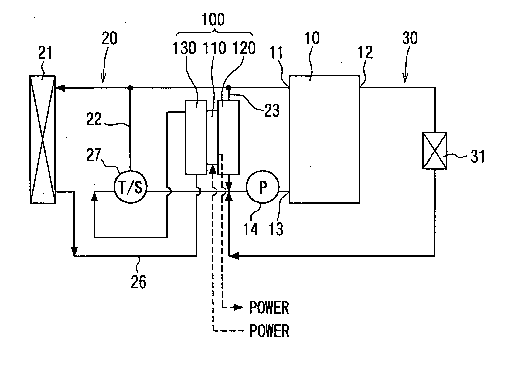
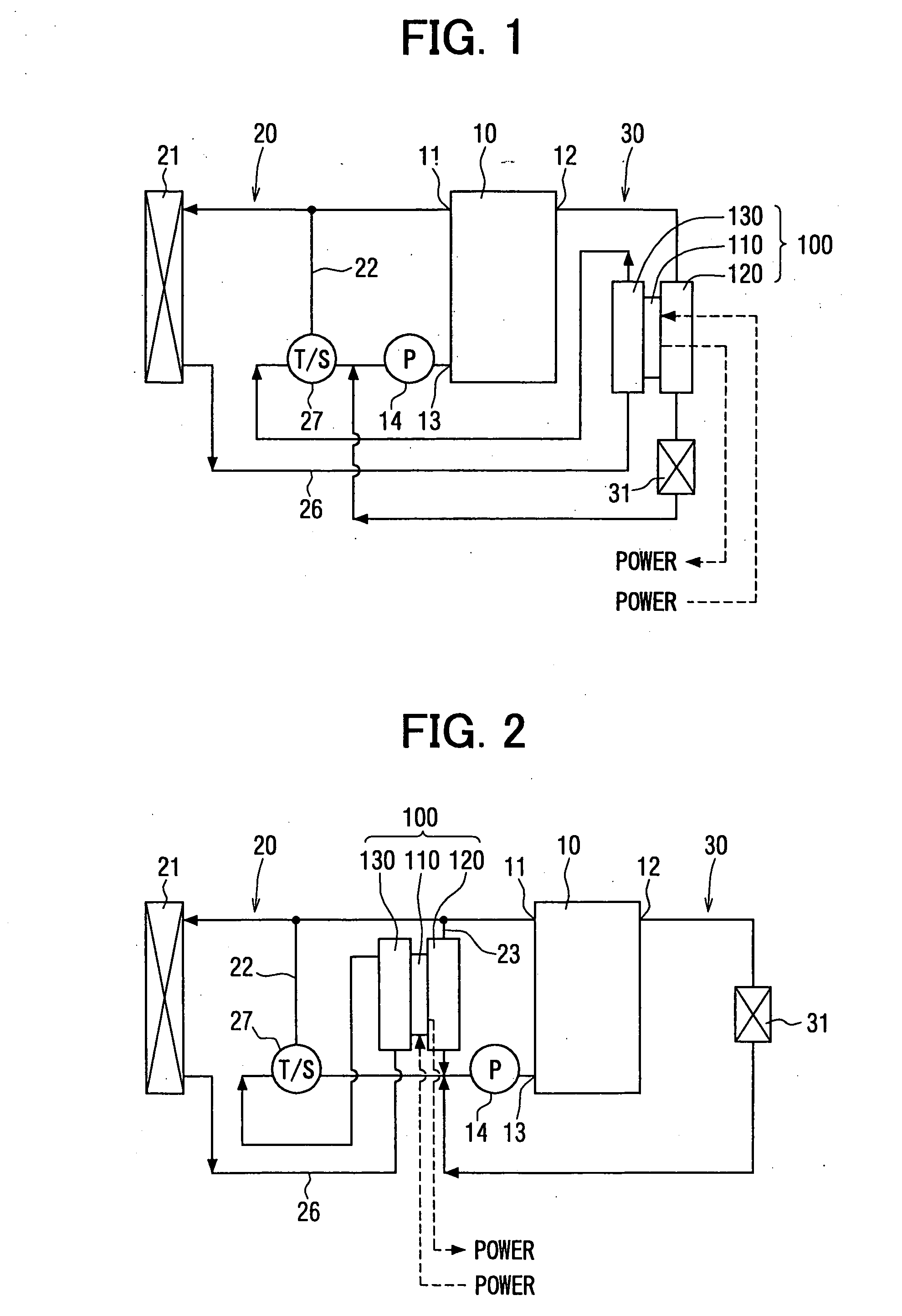
[0028] A thermoelectric power generation system 100 according to a first embodiment of the present invention will be described with reference to FIGS. 1-3. The thermoelectric power generation system 100 is suitably used in a vehicle having an engine 10 of a water-cooling type, to recover waste heat of the engine 10 and convert heat energy into electric energy.
[0029] The thermoelectric power generation system 100 has a high-temperature side heat source unit 120, a low-temperature side heat source unit 130, and a thermoelectric unit 110 having two side surfaces which respectively tightly contact the high-temperature side and low-temperature side heat source units 120, 130. Cooling water of the engine 10 is circulated to flow through the high-temperature side heat source unit 120 and the low-temperature side heat source unit 130, to be used as a high-temperature side heat source and low-temperature side heat source of the thermoelectric unit 110.
[0030] Each of the high-temperature si...
second embodiment
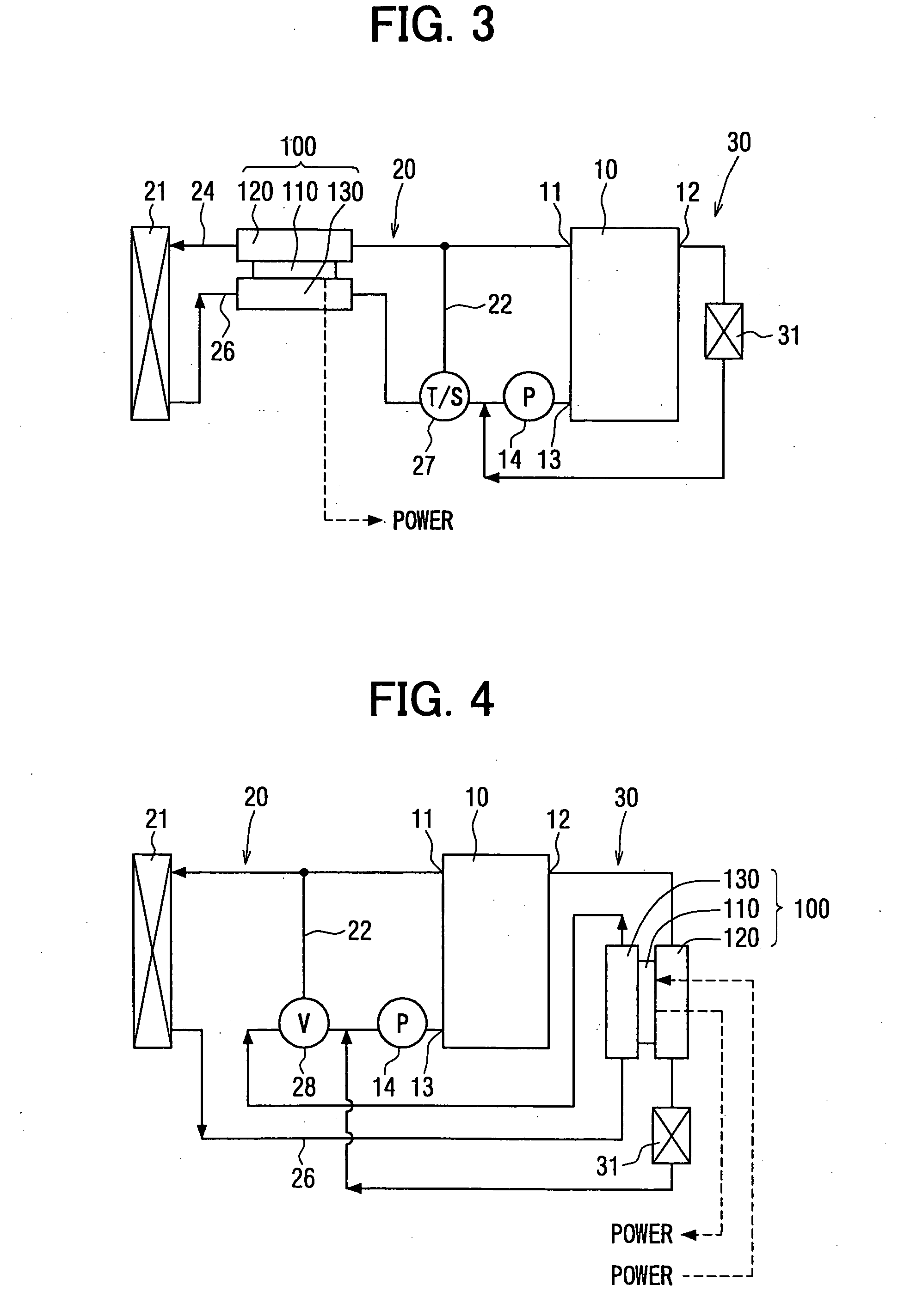
[0059] A second embodiment of the present invention will be described referring to FIG. 4. In this case, a flow-amount adjusting valve 28, the opening degree of which is controlled by a control unit (not shown), is used instead of the thermostat 27 in the above-described first embodiment.
[0060] The flow-amount adjusting valve 28, being arranged in the engine cooling-water circuit 20, is a three-way electromagnetic valve connected with the sides of the radiator 21, the bypass passage 22 and the engine 10. The opening degree of the flow-amount adjusting valve 28 at the side of the bypass passage 22 can be adjusted by the control unit from 100% to 0%, while the opening degree thereof at the side of the radiator 21 can be adjusted from 0% to 100% responding to the opening degree thereof at the side of the bypass passage 22. In this case, the sides of the radiator 21 and the bypass passage 22 are separately connected with the side of the engine 10 through the flow-amount adjusting valve...
third embodiment
[0062] A third embodiment of the present invention will be described referring to FIGS. 5-7. In this embodiment, the arrangements of the high-temperature side and low-temperature side heat source units 120, 130 in the engine cooling-water circuit 20 are the same with the second modification (referring to FIG. 3) of the first embodiment, while the temperature of cooling water discharged from the radiator 21 to the low-temperature side heat source unit 130 is further decreased.
[0063] The radiator 21 has an inlet side tank 212, an outlet side tank 213, and a heat radiation unit 211 arranged between the inlet and outlet side tanks 212, 213. According to the third embodiment, the heat radiation unit 211 is divided into a first heat radiation portion 211a and a second heat radiation portion 211b. The first heat radiation portion 211a has a size to maintain a predetermined heat radiation capacity. For example, the first heat radiation portion 211a has a size being 70% of that of the heat ...
PUM
 Abstract
Description
Claims
Application Information