Method and apparatus for plating substrates

a substrate and plating technology, applied in the direction of electrolysis components, coatings, liquid/solution decomposition chemical coatings, etc., can solve the problem of substrate wobble, and achieve the effect of reducing the amount of friction

Inactive Publication Date: 2005-12-01
WD MEDIA +1
View PDF47 Cites 90 Cited by
  • Summary
  • Abstract
  • Description
  • Claims
  • Application Information

AI Technical Summary

Benefits of technology

[0007] At least one of the mandrels is removable to facilitate loading and unloading of the substrates from the holding structure. The substrates can be magnetic disk substrates having a central opening therein. Because of the manner in which the substrates are held at their outer edges, it is easier to load and unload the substrates compared to earlier substrate plating apparatus in which the substrates were held by a dowel extending through their central opening.
[0008] In one embodiment, each set is held by one side of the central mandrel and an associated set of one or more outer mandrels. (The mandrels hold the set of substrates at the outer edges of the substrates.) Thus, a plurality of sets of substrates abuts the central mandrel. In one exemplary embodiment, three sets of substrates abut the central mandrel. The first, second and third set of substrates abut a top, lower left and lower right side of the central mandrel, respectively. This arrangement of substrates permits a larger number of substrates to be held in a given volume than if the plurality of sets of substrates did not abut a common central mandrel.
[0012] An apparatus in accordance with another embodiment of the invention comprises a holder for holding one or more substrates during plating. The holder typically has a plastic exterior, and includes a plastic member for coupling with a first race of a bearing. A second race of the bearing is also plastic, and is coupled to a rotating structure that imparts motion to the holder (and therefore to the one or more substrates held by that holder). A metallic interface (typically comprising balls or rollers) is provided between the first and second races. (The metallic interface is typically passivated to prevent the interface from becoming plated during use). Of importance, the bearing permits one to avoid or minimize the motion of plastic against plastic. This reduces the amount of friction, mechanical wear, and most importantly, generation of contaminant particles in the plating bath.
[0013] In one embodiment, a bearing with metallic races (e.g. stainless steel) as well as a metallic interface is employed. In such an embodiment, the races are typically passivated. Although this embodiment may be acceptable, metal-on-metal wearing of the races and the interface may grind away the passivation, thereby exposing metallic surfaces to the plating bath and permitting the bearing to be plated. Further, contamination particles (e.g. plated material on the bearing) may be generated. Accordingly, the embodiment using plastic races may be more desirable.
[0015] A method in accordance with another embodiment of the invention comprises the act of providing one or more substrates in a holder. The holder is mechanically coupled via a bearing to apparatus for imparting motion to the holder. The holder, one or more substrates and apparatus are placed in a plating bath, and the apparatus imparts motion to the holder. In one embodiment, the holder comprises first and second plastic races, and a metallic mechanical interface (typically a set of metal balls) therebetween. As mentioned above, this reduces the amount of friction, mechanical wear and generation of contaminant particles in the plating bath.

Problems solved by technology

During plating, the substrates can wobble.
Imperfections may result if they touch one another.

Method used


Image

  • Method and apparatus for plating substrates
  • Method and apparatus for plating substrates
  • Method and apparatus for plating substrates

Examples


Embodiment Construction

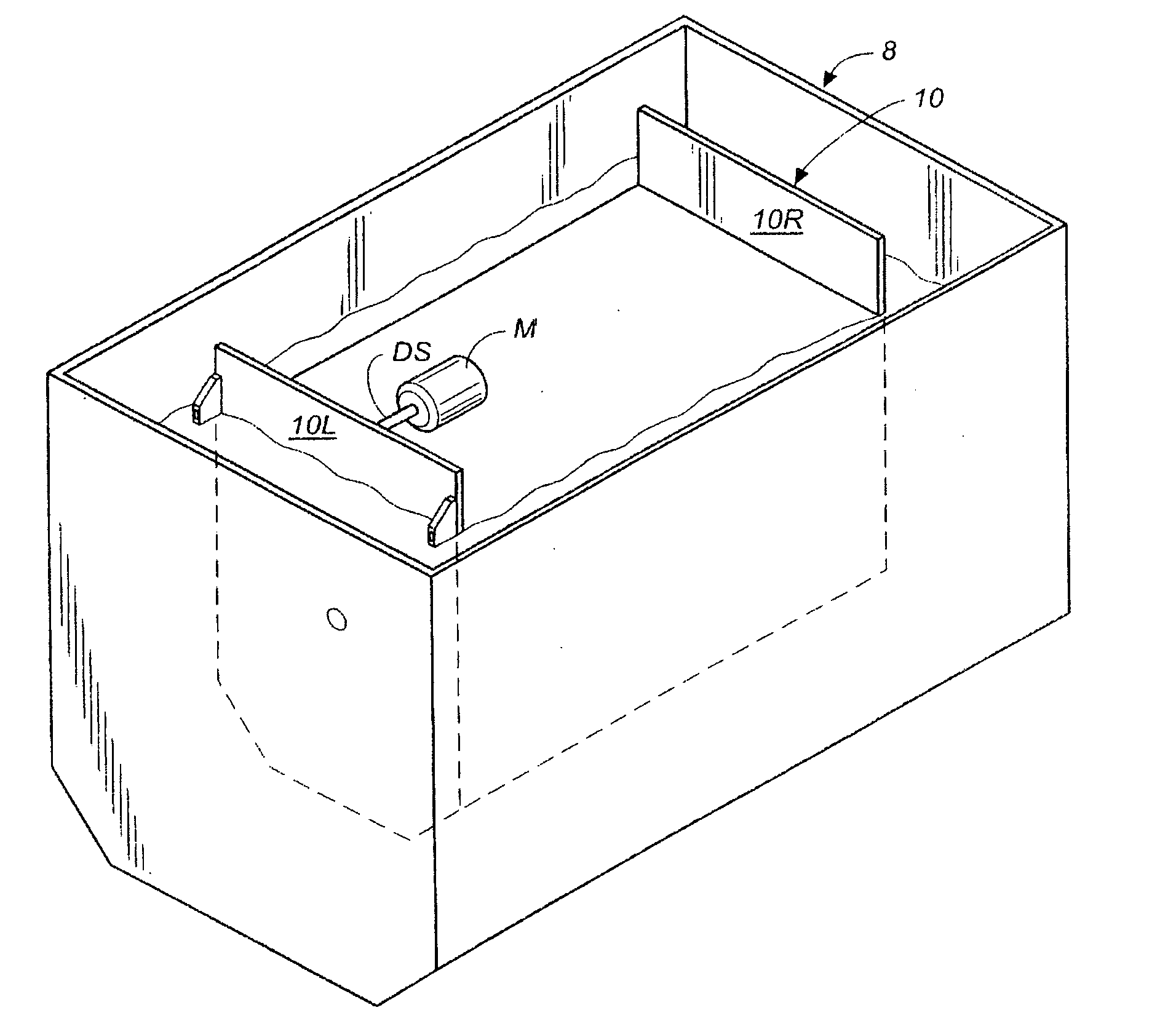
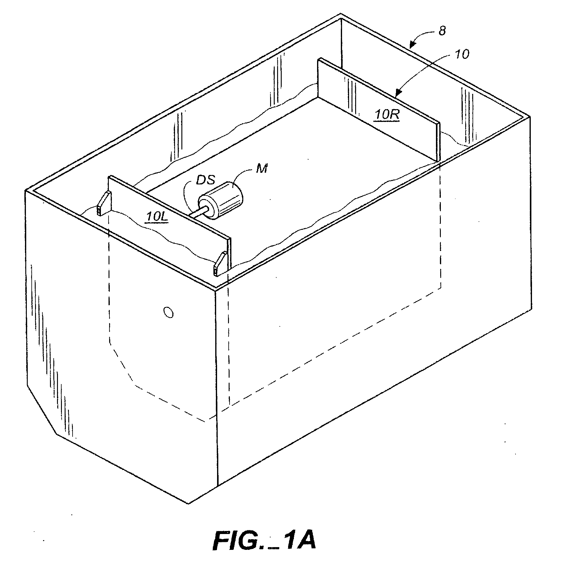
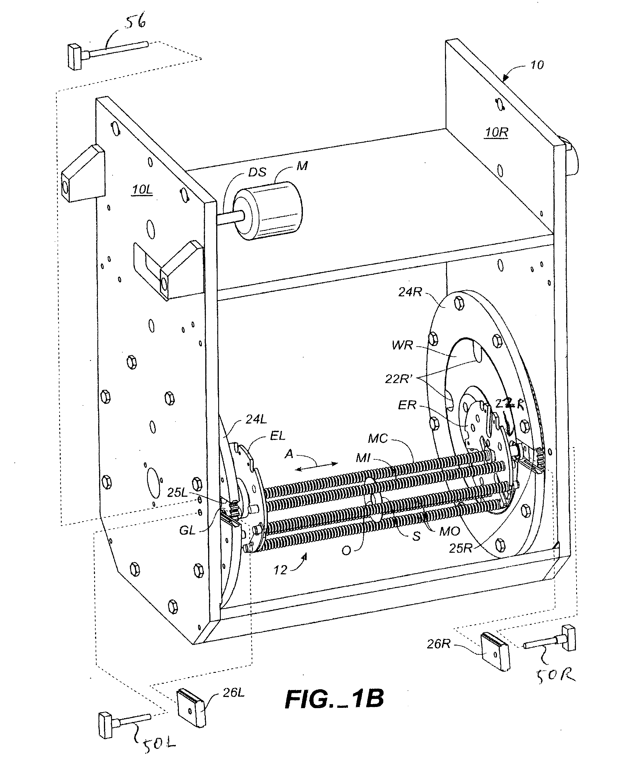
[0028] Referring to FIGS. 1 and 5, a plating bath 8 contains apparatus 10 for holding and moving substrates S during a plating process. (FIGS. 1B and 1C only show one substrate S. However, typically many substrates are plated simultaneously.) In one embodiment, the substrates comprise an aluminum alloy, and during plating, a layer (typically a metallic layer such as a nickel-phosphorus alloy) is deposited on substrates S. However, in other embodiments, substrates S can comprise other materials, and other types of layers can plated onto substrates S.

[0029] In one embodiment, substrates S are disk-shaped, and can include a centrally defined opening O therein. However, in other embodiments, substrates S have other shapes.

[0030] The plating process can be electroless plating or electroplating. Optionally, in the case of electroless plating one can apply a strike voltage to substrates S to facilitate initiation of plating. Alternatively, in some embodiments, a strike voltage is not app...


PUM

PropertyMeasurementUnit
mechanicalaaaaaaaaaa
mechanical interfaceaaaaaaaaaa
volumeaaaaaaaaaa

Abstract

Plating apparatus comprises a gear mechanism for imparting planetary motion to a set of holders for holding substrates in a plating bath. The holders are typically a non-conductive material such as plastic. The holders are coupled to a bearing comprising first and second plastic races and metallic balls therebetween. This embodiment reduces the amount of plastic moving against plastic, and therefore reduces the amount of wear, friction, and generation of contaminant parts. The holders comprise a central mandrel and outer mandrels connected to end pieces. The substrates are held at their outer edges between the outer mandrels and the central mandrels.

Description

CROSS-REFERENCE TO RELATED APPLICATION [0001] This Application is a continuation-in-part of co-pending U.S. Patent Application Ser. No. 10 / 853,953, filed May 26, 2004, incorporated herein by reference.BACKGROUND OF THE INVENTION [0002] This invention relates to methods and apparatus for plating substrates. [0003] There are various manufacturing processes during which one plates substrates. For example, during some processes for making magnetic disks, one places an aluminum alloy substrate in a plating bath to electroless plate a nickel-phosphorus alloy layer onto the substrate. Thereafter, the plated substrate is polished and textured, and one or more underlayers, one or more magnetic layers, and one or more protective overcoats are deposited (e.g. by sputtering) onto the plated substrate. (During some manufacturing processes, other layers are deposited onto the substrate as well.) Merely by way of example, one method for polishing a substrate is discussed in U.S. Pat. No. 6,149,696...

Claims


Application Information

Patent Timeline
Patent Type & Authority Applications(United States)
IPC IPC(8): C23C18/31C25D17/00C25D17/08
CPCC25D17/08
Inventor OLSEN, GERALDKNOX, DAVIDTIERNEY, ROBERTCALCATERRA, ANTHONY D.
Owner WD MEDIA
Why Eureka
Try Eureka