Plasma display panel

a plasma display and panel technology, applied in the direction of discharge tube main electrodes, discharge electrodes, gas-filled discharge tubes, etc., to achieve the effect of improving light emission efficiency, improving opening ratio, and improving brightness

Inactive Publication Date: 2005-12-01
SAMSUNG SDI CO LTD
View PDF13 Cites 5 Cited by
  • Summary
  • Abstract
  • Description
  • Claims
  • Application Information

AI Technical Summary

Benefits of technology

[0007] It is also an object of the present invention to provide a design for a that allows for nearly all of the visible light produced by the phosphor layers to be viewed by a viewer.
[0008] It is yet an object of the present invention to provide a design for a PDP that has fewer light-obstructing elements on the transparent substrate through which the visible image is viewed.
[0009] It is still an object of the present invention to provide a design for a PDP that improves upon the opening ratio.
[0010] It is further an object of the present invention to provide a design for a PDP that provides improved brightness and improved light emission efficiency.

Problems solved by technology

Unfortunately, the electrodes are formed on the substrate and thus in the path through which the visible light travels.

Method used


Image

  • Plasma display panel
  • Plasma display panel
  • Plasma display panel

Examples


Embodiment Construction

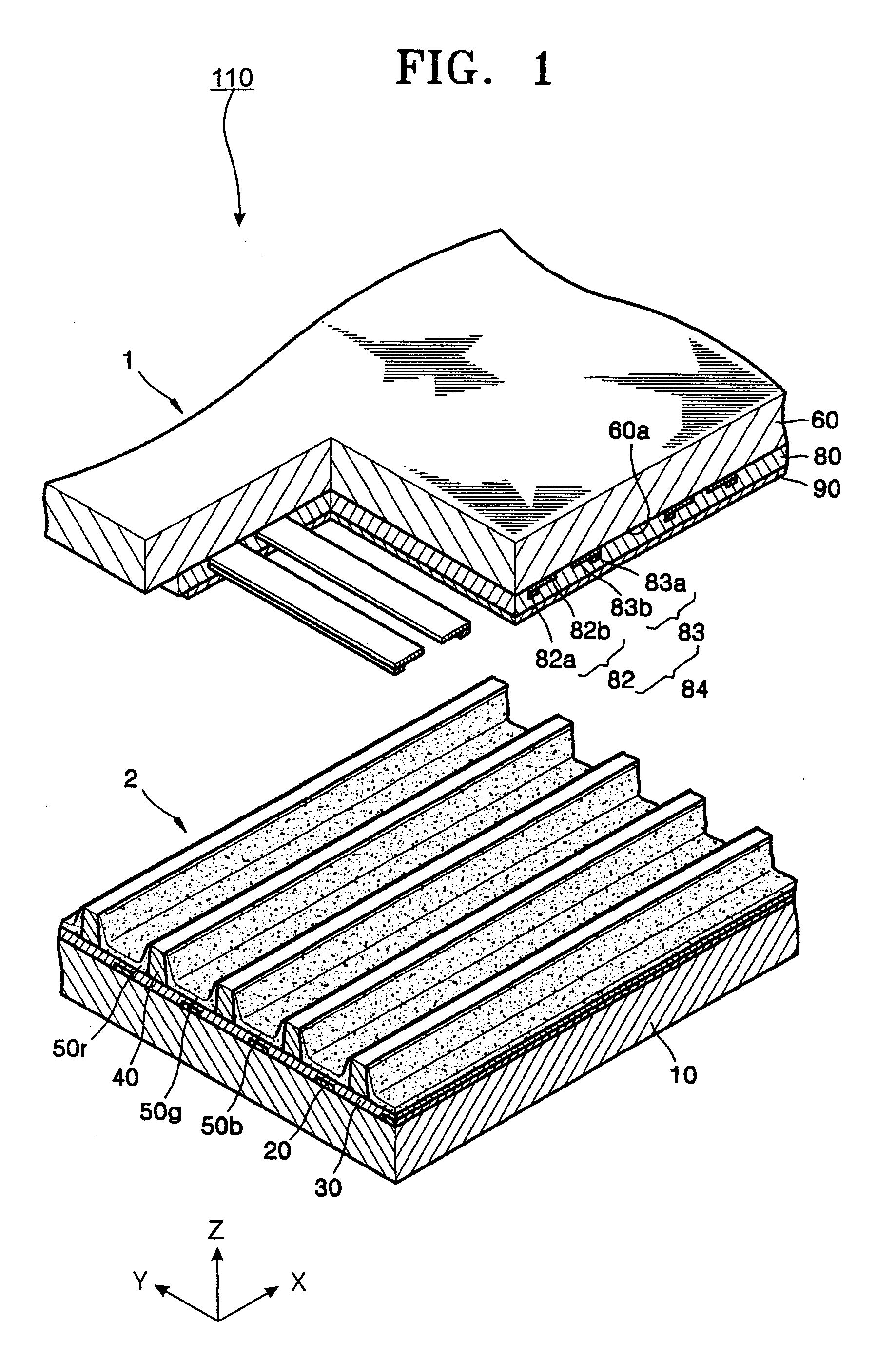
[0022] Turning now to the figures, FIG. 1 is a cutaway exploded perspective view of a PDP 110 similar to that disclosed in Japanese Patent Laid-Open publication 1998-172442. Referring to FIG. 1, PDP 110 has an upper panel 1 that is coupled with a lower panel 2, and a discharge gas that is filled in a space defined by the upper panel 1 and the lower panel 2. The upper panel 1 includes an upper substrate 60, a sustain electrode pair 84 that includes an X electrode 82 and a Y electrode 83 formed on a lower surface 60a of the upper substrate 60 and an upper dielectric layer 80 that covers the sustain electrode pair 84. The upper dielectric layer 80 can be covered by a protection layer 90 ordinarily made of MgO. The Y electrode 83 includes a first transparent electrode 83b formed of ITO (Indium Tin Oxide) and a first bus electrode 83a that serves to reduce the voltage drop along the first transparent electrode 83b. Similarly, the X electrode 82 also includes a second transparent electrod...


PUM


Abstract

Provided is a plasma display panel (PDP) design that results in improved light emission efficiency and improved brightness and improved opening ratio. The PDP includes a transparent upper substrate, a lower substrate oriented parallel to the upper substrate, a first discharge electrode extending in a first direction on the lower substrate, a dielectric layer that covers the first discharge electrode, a plurality of barrier ribs made of a dielectric material between the upper and lower substrates dividing a space between the upper and the lower substrate into a plurality of discharge cells, a second discharge electrode within the barrier ribs and extending in a second direction to cross the first discharge electrode, a phosphor layer located within the discharge cell, and a discharge gas located within the discharge cell.

Description

CLAIM OF PRIORITY [0001] This application makes reference to, incorporates the same herein, and claims all benefits accruing under 35 U.S.C. §119 from an application for PLASMA DISPLAY PANEL earlier filed in the Korean Intellectual Property Office on 31 May 2004 and there duly assigned Serial No. 10-2004-0039254. BACKGROUND OF THE INVENTION [0002] 1. Field of the Invention [0003] The present invention relates to a novel plasma display panel (PDP) design having improved opening ratio, brightness and light emission efficiency. [0004] 2. Description of the Related Art [0005] PDPs have two substrates, one being transparent. Between the two substrates are the discharge cells containing fluorescent material and a discharge gas. Ultraviolet light generated in the plasma between the two substrates is converted into visible light by the fluorescent material. This visible light must then travel through one of the two substrates to be viewed. However, in order to generate the plasma, electrode...

Claims


Application Information

Patent Timeline
Patent Type & Authority Applications(United States)
IPC IPC(8): H01J1/32H01J11/12H01J11/16H01J11/22H01J11/24H01J11/26H01J11/32H01J11/34H01J11/36H01J11/40H01J11/42
CPCH01J11/16H01J2211/36H01J2211/245H01J11/24H01J11/36H01J11/38H01J11/42
Inventor KANG, KYOUNG-DOO
Owner SAMSUNG SDI CO LTD
Why Eureka
Try Eureka