Matching unit and receiver apparatus using the same

a technology of matching unit and receiver, applied in the direction of filter, multi-port network, transmission, etc., can solve the problem that the conventional portable device cannot be carried easily, and achieve the effect of small loss

Inactive Publication Date: 2005-12-01
PANASONIC CORP
View PDF8 Cites 24 Cited by
  • Summary
  • Abstract
  • Description
  • Claims
  • Application Information

AI Technical Summary

Benefits of technology

[0015] This matching device can supply a signal in the second frequency band received by the antenna to the receiving section with a s

Problems solved by technology

The conventional portable device is not carried easily since including such separate antennas, antenn

Method used


Image

  • Matching unit and receiver apparatus using the same
  • Matching unit and receiver apparatus using the same
  • Matching unit and receiver apparatus using the same

Examples


exemplary embodiment 1

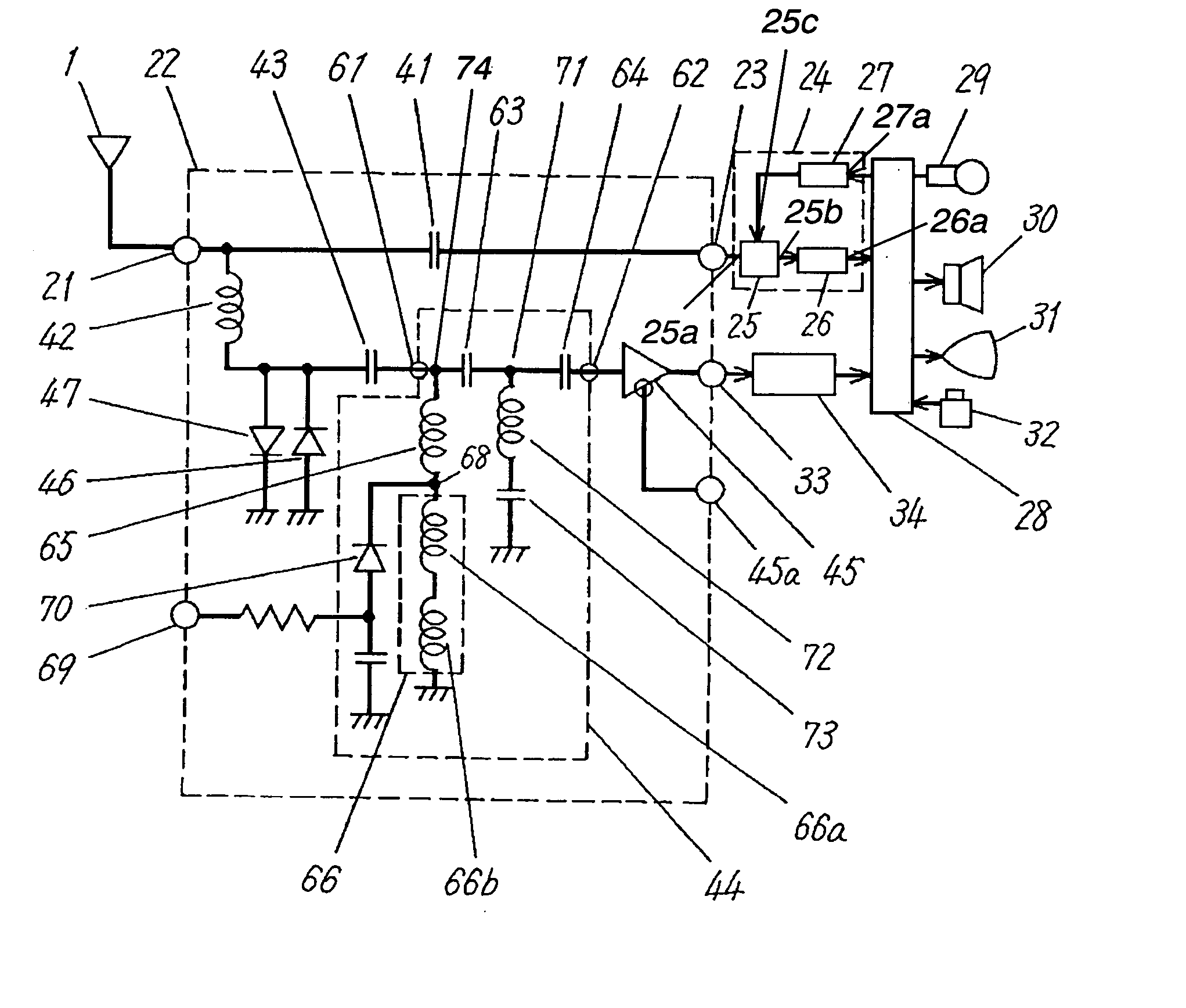
[0040]FIG. 1 is a block diagram of a portable receiver according to Exemplary Embodiment 1 of the present invention. Antenna 1 for a mobile phone receives a high frequency signal of about 820 MHz to 900 MHz, a mobile-phone signal. Antenna 1 accordingly has a length of about ¼ wavelengths of the signal, i.e., about 70 mm, so as to have an impedance of 50 Ω at the frequency of the mobile-phone signal. Antenna 1 is also used to receive TV broadcasts in VHF and UHF broadcast bands. Antenna 1 receives TV broadcast signals ranging from a lower limit frequency in the VHF broadcast band (about 50 MHz) to an upper limit frequency in the UHF broadcast band (about 770 MHz), and mobile-phone signals of about 820 MHz to 900 MHz.

[0041] Signals received by antenna 1 is supplied to input / output terminal 21 of splitter 22 also functioning as a matching device. Input / output terminal 23 outputs a mobile-phone signal out of the signals supplied to input / output terminal 21. The mobile-phone signal from...

exemplary embodiment 2

[0095]FIG. 10 is a block diagram of a portable receiver according to Exemplary Embodiment 2 of the present invention. In FIG. 10, the same elements as those shown in FIG. 1 will be denoted by the same reference numerals and their description will be briefed. The receiver according to Embodiment 2 includes a diplexer functioning as a matching device capable of receiving FM broadcast and TV broadcast, and performing communication with a mobile phone. Antenna 1 receives FM broadcast signals ranging from 76 MHz to 108 MHz as well as TV broadcast signals and mobile-phone signals of about 850 MHz.

[0096] As shown in FIG. 10, antenna 1 is connected to high-frequency input / output terminal 311 of splitter 310, and input / output terminal 312 outputs mobile-phone signals. Input / output terminal 312 is connected to transmitting / receiving section 24 and supplies the mobile-phone signals to the section. Transmitting / receiving section 24 is connected to signal processor 28. In splitter 310, output t...

exemplary embodiment 3

[0151]FIG. 20 is a cross sectional view of receiver 1520 according to exemplary Embodiment 3 of the present invention. Receiver 1520 includes splitter 310 shown in FIG. 10 according to Embodiment 2.

[0152] Antenna 521 has at its end mounter 521a fixed at case 560 made of insulating material, such as resin. Tip portion 521b of mounter 521a is connected by either solder 562 or a screw to a conductor on printed circuit board 561 accommodated in case 560.

[0153] Antenna 521 has moving portion 563 between main body 521c and mounter 521a. Moving portion 563 is rotatably in two directions 1521 and 1522 supported by mounter 521a. Splitter 310 is mounted on printed circuit board 561, and antenna 521 is electrically connected to input / output terminal 311 with each other by solder 562.

[0154] In receiver 1520 having the above structure, in order to compensate a decrease of receiver sensitivity due to the directivity of antenna 521, moving portion 563 is moved so as to locate antenna 521 at a p...


PUM


Abstract

A matching device causes an antenna to match a receiving section arranged to receive a signal in a first frequency band and a signal in a second frequency band lower than the first frequency band. The matching device includes a first terminal arranged to be connected to the antenna, a first inductor connected between the first terminal and a first node, a second inductor connected between the first node and a ground, a first capacitor connected between the first node and a second node, a second terminal arranged to be connected to the receiving section, the second terminal being connected to the second node, and a third inductor connected between the second node and the ground. The second inductor has a capacitive impedance in the first frequency band, and has an inductive impedance in the second frequency band. This matching device can supply a signal in the second frequency band received by the antenna to the receiving section with a small loss. The antenna having a small length can receive a signal of low frequencies and long wavelengths in the second frequency band.

Description

TECHNICAL FIELD [0001] The present invention relates to a matching device enabling a small antenna to receive high-frequency signals, and to a receiver including the matching device. BACKGROUND ART [0002] Portable communication devices, such as mobile phones, have been recently expected to have multifunction. Particularly according to start of terrestrial digital broadcasting creates new demand for watching television (TV) broadcasts on mobile phones. Japanese Patent Laid-Open Publication No. 2001-526483 and Japanese Patent Laid-Open Publication No. 2003-188952 disclose such multifunctional communication devices. [0003] A conventional portable receiver will be described below. FIG. 22 is a block diagram of the conventional portable receiver. [0004] Antenna 1 for a mobile phone receives a mobile-phone signal, a high frequency signal of about 850 MHz. Antenna 1 has a length of about ¼ wavelengths (about 70 mm) of the signal so as to have an impedance of 50 Ω at the frequency of the si...

Claims


Application Information

Patent Timeline
IPC IPC(8): H01Q1/24H03H7/075H03H7/38H03H7/46H04B1/18
CPCH01Q1/242H01Q1/244H03H7/38H04B1/18H03H2007/386H03H2250/00H04B1/005H03H7/46
Inventor HIBINO, YASUHIROKAMIMOTO, RYUICHIITO, AKIRA
Owner PANASONIC CORP
Why Eureka
Try Eureka