Apparatus for detecting arc fault

a technology for detecting arc faults and apparatus, applied in emergency protective arrangements, emergency protective arrangements for limiting excess voltage/current, electrical equipment, etc., can solve problems such as fire, many fires, and faults in cables

Inactive Publication Date: 2005-12-01
SEOCHANG ELECTRONIC COMMUNICATION CO LTD
View PDF10 Cites 22 Cited by
  • Summary
  • Abstract
  • Description
  • Claims
  • Application Information

AI Technical Summary

Benefits of technology

[0017] Therefore, the present invention has been made in view of the above problems, and it is an object of the present invention to provide an apparatus for detecting an arc fault in order to prevent a fault trip by making a distinction between an arc signal and signals occurred when operating a dimmer and when starting electric equipment.
[0019] It is yet another object of the present invention to provide an apparatus for detecting an arc fault, which amplitudes a detected signal, determines a frequency component and detects an arc signal in order to understand a frequency characteristic of the detected signal more precisely.

Problems solved by technology

Such cables may suffer from faults caused by a thermal degradation, an aging, humidity or animals such as rats or squirrels.
Firstly, in case that a load current is over the rating current, the current flowing in the circuit breaker is higher than normal current and it causes heat.
Secondly, in case that a phase-to-phase short circuit occurs in the load side by an electric tool or other metal material, an high voltage is generated instantaneously and then the Bimetal is heated.
Even though the miniature circuit breakers and the earth leakage breakers are established and used, many fires broke out all over the world every year.
Since this arc fault is of a low current and a high impedance and generates a current having a root mean square (RMS) less than a thermal threshold of the breaker, the cable cutting apparatus may not respond to the fault and therefore a fire breaks out in many cases.
Nevertheless, the arc fault is very dangerous since it occurs in a high temperature.
Causes of arc fault are very various, for example, an aging, breakdowns of insulation and wire, a mechanical and electrical stress by an excessive usage or an excessive voltage, an connection fault, and an excessive mechanical fault to wires.
When an arc occurs in this state, a lot of heat occurs in the cable locally.
And when the heat continues to occur enough to break or carbonize an insulator adjacent to the arc occurring area, a fire would break out.
When the aging phenomenon of the cable continues for a long time as described above, the cover of the cable is damaged due to the carbonization of the cable, and the joule heating is generated due to the arc current so that the cable is aged more severely.
Referring to the arc detector, the most difficult problem is a signal when starting electric equipment and a signal from a dimmer.
Both signals are nearly similar in their forms so that a conventional arc fault detector misconceives the signals occurred when starting the electrical equipment and occurred by the dimmer as an arc and often breaks the circuit.
Accordingly, the conventional apparatus for detecting an arc fault has a problem that it misconceives a signal occurred when operating the dimmer as an arc signal and breaks a fixed circuit.
Also, since the signal occurred when operating the dimmer is nearly similar with that of an arc signal in their magnitude, an apparatus for detecting the arc using a magnitude of the conventional signal cannot make a distinction between a harmful arc and a signal occurred when operating the dimmer.

Method used


Image

  • Apparatus for detecting arc fault
  • Apparatus for detecting arc fault
  • Apparatus for detecting arc fault

Examples


third embodiment

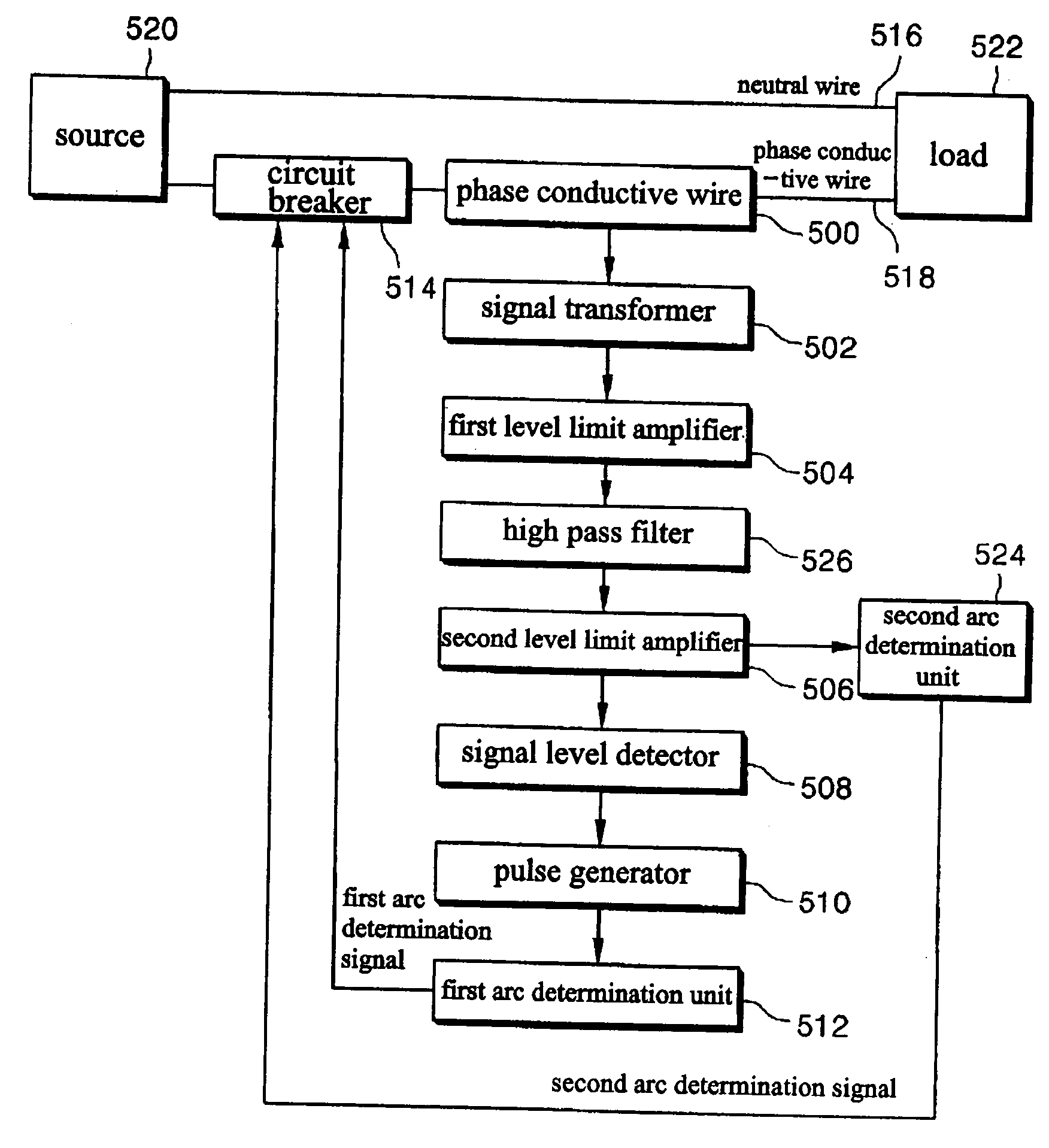
[0167]FIG. 28 is a block diagram showing an apparatus for detecting an arc fault in accordance with the present invention. Referring to FIG. 28, the apparatus includes an arc determination unit 715 for determining whether an arc signal detected by a phase conductive wire 418 of a circuit connecting a source and a load is a harmful arc signal, a neutral wire detector 700 for blocking a neutral wire 414 and the phase conductive wire 416 depending on a state detection result of the neutral wire to which a power is supplied from the source terminal and a control of the arc determination unit 715, a first current detector 701 for detecting an RF current flowing through the phase conductive wire 418, a first arc detector 710 for amplifying a weak RF signal outputted from the first current detector 701 and removing an unnecessary RF signal to detect the arc signal and output the detected arc signal to the arc determination unit 715, a second current detector 702 for detecting variation of ...

fourth embodiment

[0195]FIG. 29 is a block diagram of an apparatus of detecting an arc fault according to the present invention. Referring to FIG. 4, the apparatus includes an arc determination unit 715 for determining whether an arc signal detected by a phase conductive wire 418 of a circuit connecting a source and a load is a harmful arc signal, a neutral wire detector 700 for blocking a neutral wire 414 and the phase conductive wire 416 depending on a state detection result of the neutral wire to which a power is supplied from the source terminal and a control of the arc determination unit 715, a third current detector 703 for detecting variation of current flowing through the phase conductive wire 418 and generating a signal in proportional to the variation of the current, 21st and 22nd amplifiers and 21st and 22nd filters 741 through 744 for amplifying and filtering an output signal of the third current detector 703 and outputting the amplified and filtered signal to the arc determination unit 7...


PUM


Abstract

An apparatus for detecting an arc fault. The apparatus comprises a current detector for detecting the amount of change of current flowing on the wire and generating a signal proportional to the amount of change; a signal transformer for passing a high frequency component of the signal outputted from the current detector, and limiting a level of the signal not to exceed a fixed signal level; a first level limit amplifier for amplifying a signal outputted from the signal transformer so as to limit the level of the outputted signal; a signal level detector for determining whether a input signal exceeds a fixed first voltage and generating a detection signal; a pulse generator for transforming the detection signal outputted from the signal level detector into a form of normalized pulse; a first arc determination unit for counting a pulse signal outputted from the pulse generator for a predetermined time, determining whether the arc has been occurred and generating an arc detection signal; and a circuit breaker for breaking the conductive wire when the are detection signal is generated.

Description

FIELD OF THE INVENTION [0001] The present invention relates to an apparatus for detecting an arc fault in a distribution system, and more particularly, to an apparatus for detecting an arc fault, wherein a harmful arc causing a fire can be effectively distinguished from voltages generated when starting electrical equipment and when operating dimmers, which are frequently misconceived as an arc. BACKGROUND OF THE INVENTION [0002] Distributors in special regions including a city, an industrial area and a commercial area generally use low voltage networks of 600 volts or less. Specially, cables of the networks are laid under the ground, which are designed to inflow into it at sites more than one. Such cables may suffer from faults caused by a thermal degradation, an aging, humidity or animals such as rats or squirrels. A circuit breaker is provided in order to protect the networks from the causes. The circuit breaker is required to have cutting units such as fuses in order to isolate t...

Claims


Application Information

Patent Timeline
Patent Type & Authority Applications(United States)
IPC IPC(8): H02H1/00H02H1/04H02H3/00
CPCH02H1/04H02H1/0015
Inventor KIM, CHEON-YOUNKIM, DONG-SEBKO, JOUNG-MYOUNGMOON, JE-CHUN
Owner SEOCHANG ELECTRONIC COMMUNICATION CO LTD
Why Eureka
Try Eureka