Natural gas liquefaction

a natural gas and liquefaction technology, applied in the direction of refrigeration and liquidation, solidification, lighting and heating equipment, etc., can solve the problems of no pipeline infrastructure that would allow for convenient transportation, and little attention has been given to the efficiency of the hydrocarbon removal step

Inactive Publication Date: 2005-12-08
UOP LLC
View PDF73 Cites 85 Cited by
  • Summary
  • Abstract
  • Description
  • Claims
  • Application Information

AI Technical Summary

Benefits of technology

[0009] In accordance with the present invention, it has been found that careful integration of the hydrocarbon removal step into the LNG liquefaction process can produce both LNG and a separate heavier hydrocarbon liquid product using significantly less energy than prior art processes. The present invention, although applicable at lower pressures, is particularly advantageous when processing feed gases in the range of 400 to 1500 psia [2,758 to 10,342 kPa(a)] or higher.

Problems solved by technology

In remote locations, for instance, there is often no pipeline infrastructure that would allow for convenient transportation of the natural gas to market.
Unfortunately, little attention has been focused heretofore on the efficiency of the hydrocarbon removal step.

Method used


Image

  • Natural gas liquefaction
  • Natural gas liquefaction
  • Natural gas liquefaction

Examples


example 1

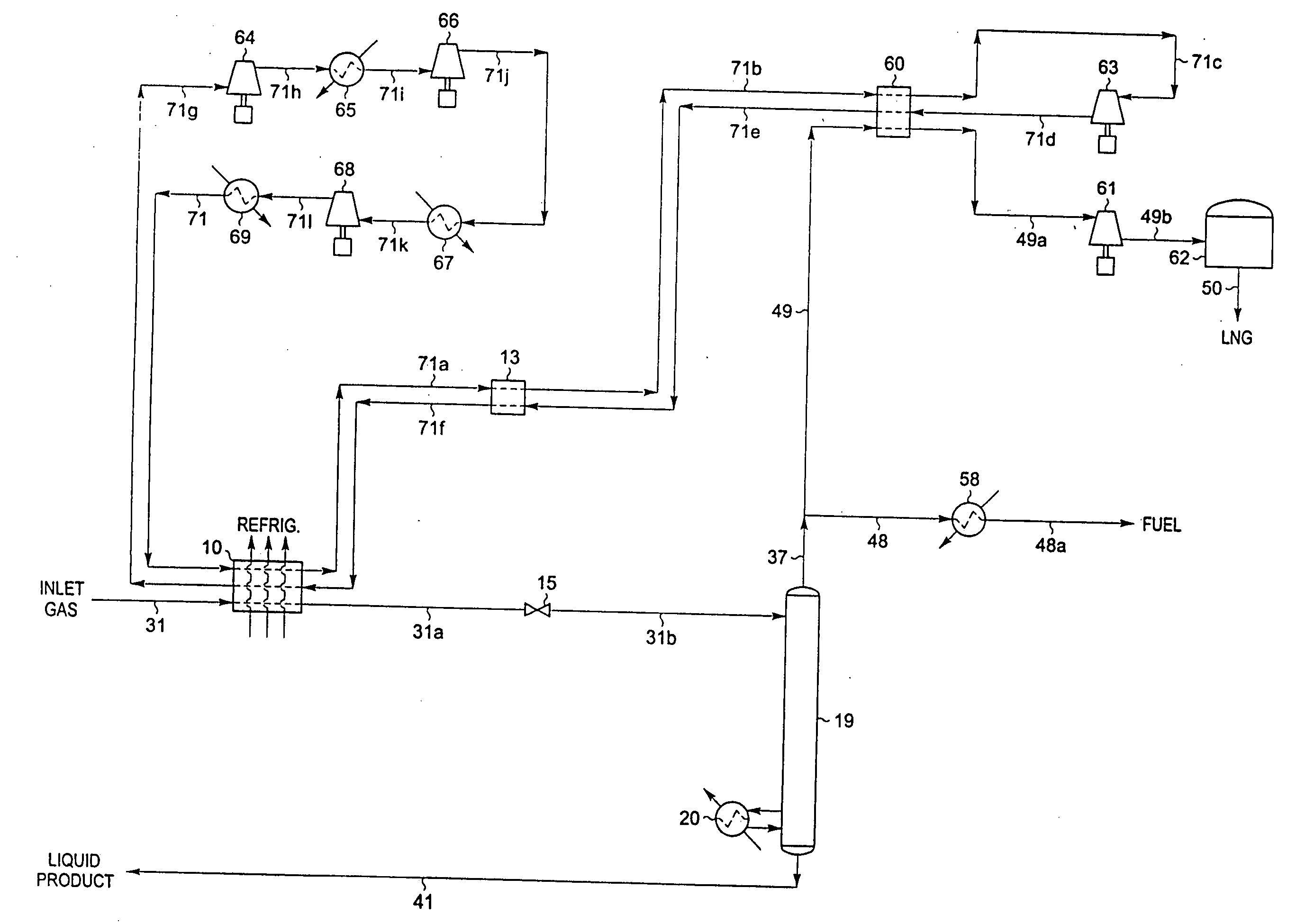
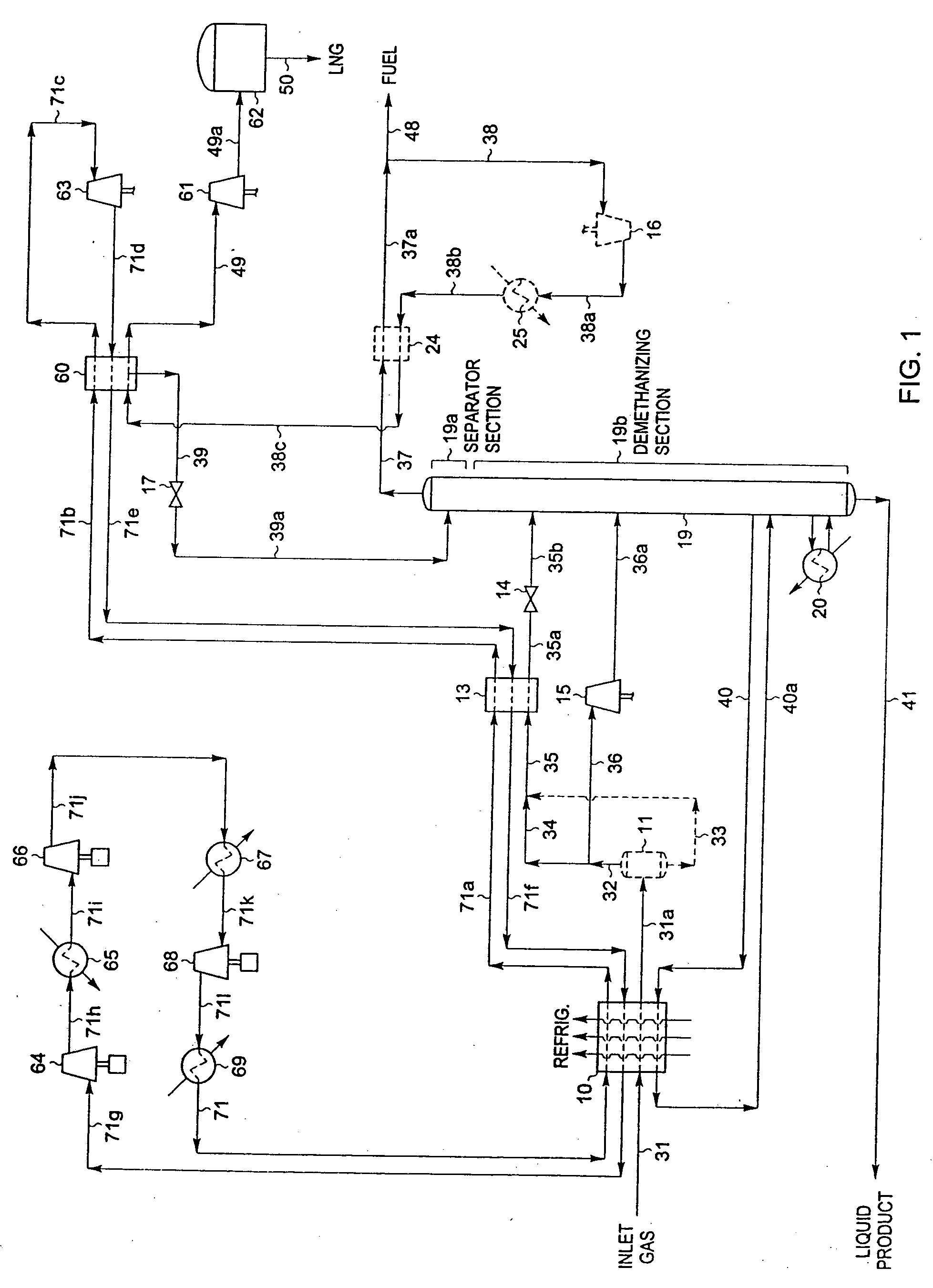
[0034] Referring now to FIG. 1, we begin with an illustration of a process in accordance with the present invention where it is desired to produce an NGL co-product containing the majority of the ethane and heavier components in the natural gas feed stream. In this simulation of the present invention, inlet gas enters the plant at 90° F. [32° C.] and 1285 psia [8,860 kPa(a)] as stream 31. If the inlet gas contains a concentration of carbon dioxide and / or sulfur compounds which would prevent the product streams from meeting specifications, these compounds are removed by appropriate pretreatment of the feed gas (not illustrated). In addition, the feed stream is usually dehydrated to prevent hydrate (ice) formation under cryogenic conditions. Solid desiccant has typically been used for this purpose.

[0035] The feed stream 31 is cooled in heat exchanger 10 by heat exchange with refrigerant streams and demethanizer side reboiler liquids at −68° F. [−55° C.] (stream 40). Note that in all ...

example 2

[0050] If the specifications for the LNG product will allow more of the ethane contained in the feed gas to be recovered in the LNG product, a simpler embodiment of the present invention may be employed. FIG. 3 illustrates such an alternative embodiment. The inlet gas composition and conditions considered in the process presented in FIG. 3 are the same as those in FIG. 1. Accordingly, the FIG. 3 process can be compared to the embodiment displayed in FIG. 1.

[0051] In the simulation of the FIG. 3 process, the inlet gas cooling, separation, and expansion scheme for the NGL recovery section is essentially the same as that used in FIG. 1. Inlet gas enters the plant at 90° F. [32° C.] and 1285 psia [8,860 kPa(a)] as stream 31 and is cooled in heat exchanger 10 by heat exchange with refrigerant streams and demethanizer side reboiler liquids at −35° F. [−37° C.] (stream 40). The cooled stream 31a enters separator 11 at −30° F. [−34° C.] and 1278 psia [8,812 kPa(a)] where the vapor (stream ...

example 3

[0062] If the specifications for the LNG product will allow all of the ethane contained in the feed gas to be recovered in the LNG product, or if there is no market for a liquid co-product containing ethane, an alternative embodiment of the present invention such as that shown in FIG. 4 may be employed to produce an LPG co-product stream. The inlet gas composition and conditions considered in the process presented in FIG. 4 are the same as those in FIGS. 1 and 3. Accordingly, the FIG. 4 process can be compared to the embodiments displayed in FIGS. 1 and 3.

[0063] In the simulation of the FIG. 4 process, inlet gas enters the plant at 90° F. [32° C.] and 1285 psia [8,860 kPa(a)] as stream 31 and is cooled in heat exchanger 10 by heat exchange with refrigerant streams and flashed separator liquids at −46° F. [−43° C.] (stream 33a). The cooled stream 31a enters separator 11 at −1° F. [−18° C.] and 1278 psia [8,812 kPa(a)] where the vapor (stream 32) is separated from the condensed liqui...


PUM


Abstract

A process for liquefying natural gas in conjunction with producing a liquid stream containing predominantly hydrocarbons heavier than methane is disclosed. In the process, the natural gas stream to be liquefied is partially cooled, expanded to an intermediate pressure, and supplied to a distillation column. The bottom product from this distillation column preferentially contains the majority of any hydrocarbons heavier than methane that would otherwise reduce the purity of the liquefied natural gas. The residual gas stream from the distillation column is compressed to a higher intermediate pressure, cooled under pressure to condense it, and then expanded to low pressure to form the liquefied natural gas stream.

Description

CROSS REFERENCE TO RELATED APPLICATIONS [0001] This is a divisional of U.S. patent application Ser. No. 10 / 823,248, filed on Apr. 13, 2004 which is a divisional of U.S. patent application Ser. No. 10 / 161,780, filed on Jun. 4, 2002, which claims priority under 35 U.S.C. § 199(e) to U.S. Provisional Patent Application No. 60 / 296,848, filed on Jun. 8, 2001.BACKGROUND OF THE INVENTION [0002] This invention relates to a process for processing natural gas or other methane-rich gas streams to produce a liquefied natural gas (LNG) stream that has a high methane purity and a liquid stream containing predominantly hydrocarbons heavier than methane. The applicants claim the benefits under Title 35, United States Code, Section 119(e) of prior U.S. provisional application Ser. No. 60 / 296,848 which was filed on Jun. 8, 2001. [0003] Natural gas is typically recovered from wells drilled into underground reservoirs. It usually has a major proportion of methane, i.e., methane comprises at least 50 mo...

Claims


Application Information

Patent Timeline
Patent Type & Authority Applications(United States)
IPC IPC(8): F25J1/00F25J1/02F25J3/00F25J3/02
CPCF25J1/0205F25J1/0216F25J1/0239F25J1/0241F25J3/0209F25J3/0233F25J3/0238F25J3/0242F25J3/0247F25J2200/02F25J2200/04F25J2200/70F25J2200/72F25J2200/74F25J2200/76F25J2200/78F25J2205/04F25J2230/08F25J2230/60F25J2235/60F25J2240/02F25J2240/30F25J2240/40F25J2245/02F25J2270/02F25J2270/12F25J2270/60F25J2270/66F25J2290/40F25J2290/62F25J1/0022F25J1/0042F25J1/0052F25J1/0057F25J1/0214
Inventor WILKINSON, JOHN D.HUDSON, HANK M.CUELLER, KYLE T.
Owner UOP LLC
Why Eureka
Try Eureka