Solar cell module connector and method of producing solar cell module panel

a solar cell module and connector technology, applied in the direction of light radiation electric generators, coupling device connections, generators/motors, etc., can solve the problem of easy damage, and achieve the effect of convenient connection of cathodes

Inactive Publication Date: 2005-12-08
SANSHA ELECTRIC MFG
View PDF2 Cites 44 Cited by
  • Summary
  • Abstract
  • Description
  • Claims
  • Application Information

AI Technical Summary

Benefits of technology

[0009] Each heat sink may be provided with a socket with which the cathode of the associated diode may be connected. This arrangement makes it easier to connect the cathodes to the heat sinks.

Problems solved by technology

However, the diodes used in the Japanese publication are in the form of a mechanically weak, thin semiconductor pellet and, therefore, are easily damaged when subjected to vibrations and impact.

Method used


Image

  • Solar cell module connector and method of producing solar cell module panel
  • Solar cell module connector and method of producing solar cell module panel
  • Solar cell module connector and method of producing solar cell module panel

Examples


first embodiment

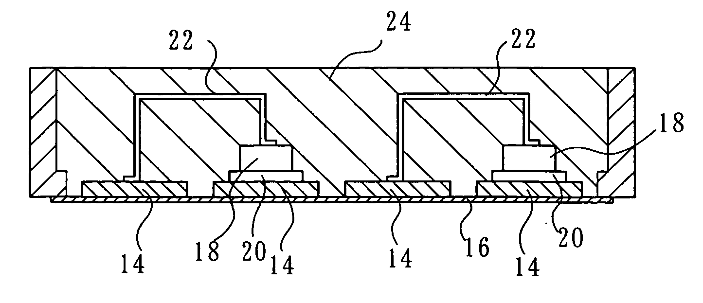
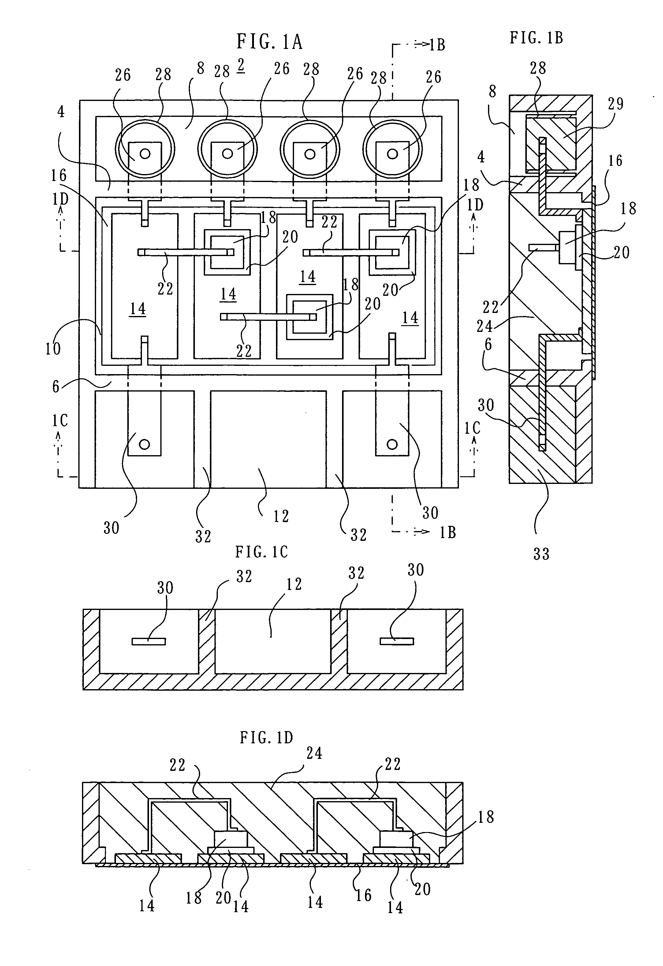
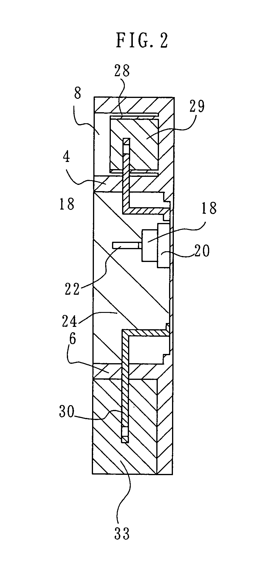
[0019] A solar cell module connector according to the present invention has an insulating box 2 as shown in FIGS. 1A through 1D. The insulating box 2 may be formed of an insulating material, e.g. an epoxy resin. Two spaced-apart partitions 4 and 6 divide the insulating box 2 into three zones, namely, a solar cell module lead line terminal zone 8, a diode heat sink zone 10, and an output cable terminal zone 12.

[0020] Plural, four, for example, heat sinks 14 are arranged in a row in the diode heat sink zone 10, being spaced from and in parallel with each other. Each of the heat sinks 14 may be a rectangular steel plate having a thickness of, for example, 3 mm. One end of each heat sink 14 is located nearer to the solar cell module lead line terminal zone 8, while the other, opposite end of each heat sink 14 is located nearer to the output cable connection terminal zone 12. The bottom of the diode heat sink zone 10 is partly or entirely removed to form an opening, and a heat-conductive...

sixth embodiment

[0040]FIG. 7 shows a connector according to the present invention. The connector includes an insulating box 100 having a diode zone in the form of, for example, a mount casing 102, a partition in the form of, for example, an insert casing 104, and a lid 106. The mount casing 102 is a flat, rectangular parallelepiped, having an opening upward, for example, and is formed of insulating material, e.g. epoxy. The insert casing 104 is disposed to close the opening of the mount casing 102, and the lid 106 is disposed on the insert casing 104.

[0041] Plural, three, for example, heat sinks 108 are spaced from each other on an upper surface of the bottom of the mount casing 102 along the length direction of the casing 102. As in the connector according to the first embodiment, openings may be formed in the bottom of the mount casing 102, with heat-conductive insulating sheets bonded to close the bottom of the openings. The heat sinks 108 are bonded to the upper surfaces of the respective ones ...


PUM


Abstract

A solar cell module connector includes an insulating box (2). The insulating box includes a solar cell module lead line connection zone (8) and an output cable connection zone (12) disposed on opposite sides of an diode zone (10), with partitions (4, 6) disposed therebetween, respectively. Heat sinks (14) are disposed in the diode zone, with their first ends located in said solar cell module lead line connection zone and with their second ends located in said output cable connection zone. Connection terminals (26) are connected to the respective ones of the first ends of the heat sinks and extend through the partition (4) into the solar cell module lead line connection zone. Connection terminals (30) are connected to the second ends of the heat sinks disposed at the opposite, first and second outermost locations and extend through the partition (6) into the output cable connection zone. Anodes of chip-type diodes (18) are connected to the respective heat sinks expect one of the two outermost heat sinks, with their cathodes connected to the respective ones of the heat sinks adjacent on the first outermost location side.

Description

[0001] This invention relates to a connector for connecting solar cell modules and a method of producing a solar cell module panel with such connector. BACKGROUND OF THE INVENTION [0002] Sometimes, in order to derive a desired magnitude of voltage, a plurality of solar cell modules are connected in series on the spot by means of solar cell module connectors. Also, bypass diodes may sometimes be connected to the respective modules in the connector. Various techniques have been developed to make such connectors thin and still electrically reliable. One example is disclosed in Japanese Patent Application Publication No. HEI 5-343724 A. [0003] According to the technique disclosed in this Japanese publication, a relay terminal carrying board is disposed in a terminal box. Two electrically conductive relay terminal connecting portions are formed, being spaced from each other, on the relay terminal carrying board. The anode of a pellet-shaped bypass diode is soldered to one of the conducti...

Claims


Application Information

Patent Timeline
Patent Type & Authority Applications(United States)
IPC IPC(8): H01L31/042H01L21/00H01L25/00H01L25/07H01L25/11H01R9/24H01R13/66H02N6/00
CPCH01L25/072H01L25/115H01R9/2425H01R13/6641H02S40/345H01L2924/0002H02S40/34H01L2924/00Y02E10/50
Inventor AOYAMA, MASAHIRO
Owner SANSHA ELECTRIC MFG
Why Eureka
Try Eureka