El device and display using same

a technology of el element and display, which is applied in the direction of discharge tube/lamp details, organic semiconductor devices, discharge tubes luminescnet screens, etc., can solve the problems of inability to keep constant distance between the upper and lower film substrates, inability to maintain the planarity of the surface and inability to keep constant distance between the film substrates on both sides of the el element parts. , to achieve the effect of uniform rigidity and thermal expansion

Inactive Publication Date: 2005-12-08
DAI NIPPON PRINTING CO LTD
View PDF7 Cites 13 Cited by
  • Summary
  • Abstract
  • Description
  • Claims
  • Application Information

AI Technical Summary

Benefits of technology

[0025] In the display according to the second aspect of the present invention, the sealant layer is formed on the whole area including the peripheral part of the EL element part. Therefore, the rigidity and thermal expansion of the whole EL element part are uniform, the distance between the film substrates on both sides of the EL element part can be kept constant, and the whole display is flexible.

Problems solved by technology

From the viewpoint of improving the protective function of the protective layer, however, when the protective layer is formed of the same member as the film substrate, as in the case of the construction using the glass substrate, the formation of a sealant layer on the peripheral part of upper and lower film substrates results in the presence of a sealant layer-formed area and a sealant layer-unformed area.
Further, in this case, the distance between the upper and lower film substrates cannot kept constant, and, thus, the planarity of the surface of the EL element cannot be sometimes maintained.
Further, the distance between the two synthetic resin sheets cannot be kept constant making it impossible to maintain the planarity of the surface of the EL element.
When the display is applied in a curved form, the first electrode, the EL layer, the second electrode and the like constituting the EL element sandwiched between the two synthetic resin sheets are pressed and are damaged.
Due to the above constructions, in these displays, letters or pictures which can be displayed are restricted making it difficult to realize displays with a free design.

Method used


Image

  • El device and display using same
  • El device and display using same
  • El device and display using same

Examples


embodiments of invention

[0032] First Aspect of Invention

[0033] A1. EL Element

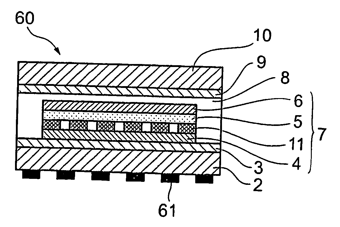
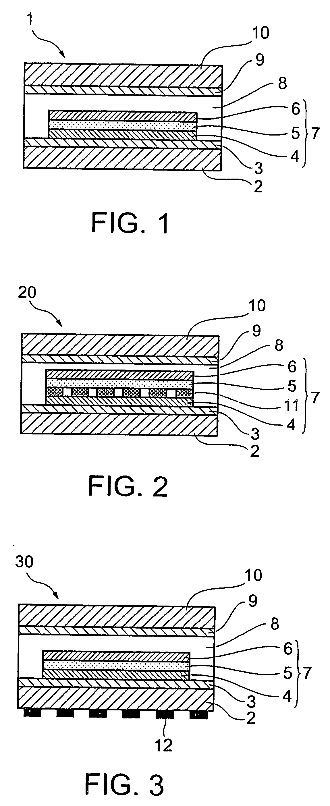
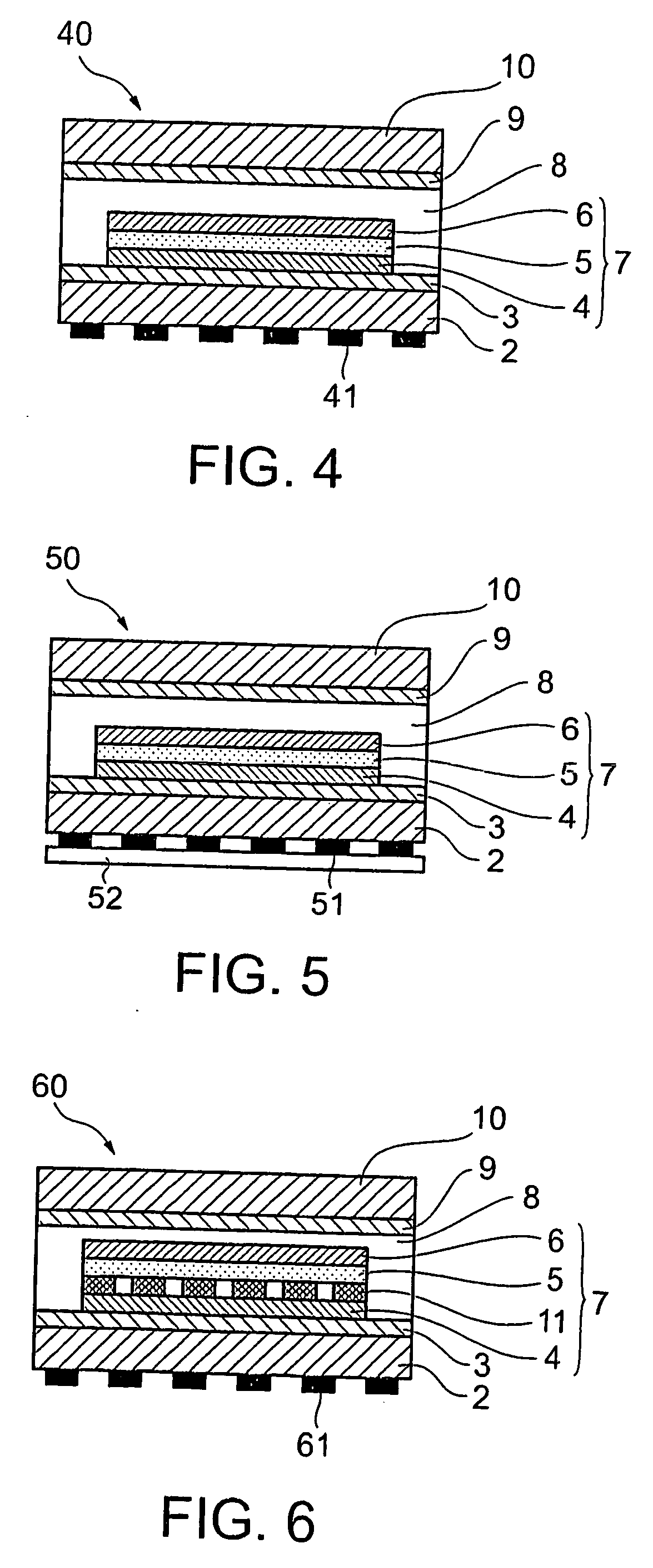
[0034] An EL element in a first aspect of the present invention will be described with reference to FIG. 1. FIG. 1 is a cross-sectional view showing a preferred embodiment of the EL element according to the present invention. As shown in FIG. 1, the EL element according to the present invention comprises a first film substrate 2, a barrier layer 3, a first electrode 4, an EL part 7 comprising a luminescent layer 5 and a second electrode, a sealant layer 8, a barrier layer 9, and a second film substrate 10. The EL part 7 is provided on the barrier layer 3 while leaving a part of the barrier layer 3 as it is without providing the EL part 7 thereon, that is, the EL part 7 is provided on a part of the barrier layer 3. A sealant layer 8 is provided as a continuous layer covering both the second electrode 6 and the barrier layer 3 in its part where the EL part 7 is not provided so that the upper surface of the sealant layer 8 is flat....


PUM

PropertyMeasurementUnit
thicknessaaaaaaaaaa
thicknessaaaaaaaaaa
thicknessaaaaaaaaaa

Abstract

Disclosed is an EL element in which the rigidity and thermal expansion of the whole EL element is homogeneous, the spacing between film substrates provided respectively on both sides of the EL element can be kept constant, and the whole EL element is flexible. The EL element comprises a first film substrate, an EL part, and a sealant layer, the EL part comprising a first electrode, an EL layer, and a second electrode and being provided on a part of a surface of the first film substrate, the sealant layer being provided to cover the EL part and to cover the EL part-free part of the surface of the first film substrate in such a manner that the sealant layer covering the EL part is contiguous with the sealant layer covering the EL part-free part of the surface of the first film substrate.

Description

BACKGROUND OF THE INVENTION [0001] 1. Field of the Invention [0002] The present invention relates to an EL element and a display using the same. [0003] 2. Background Art [0004] First Aspect of the Invention [0005] EL elements (electroluminesent elements) are self-luminous elements and are quick in response and are excellent in visibility of images, as well as in image display characteristics of moving images. In particular, organic EL elements can emit light under direct current and low voltage conditions and thus are expected to find extensive applications. [0006] The EL element generally comprises a glass substrate and a first electrode, an EL part, a second electrode, and a protective layer stacked in that order on the glass substrate. From the viewpoint of improving the function of the protective layer, however, an EL element has been developed in which, as with the glass substrate, the protective layer is formed of glass and a sealant layer is provided on the peripheral part be...

Claims


Application Information

Patent Timeline
Patent Type & Authority Applications(United States)
IPC IPC(8): H01L51/00H01L51/30H01L51/52H05B33/04
CPCH01L51/0039H01L51/005H05B33/04H01L51/5237H01L2251/5338H01L51/0077H10K59/221H10K85/115H10K85/60H10K85/30H10K50/8426H10K2102/311H05B33/12H10K50/84H10K50/85
Inventor HANDA, SHINICHINAKAJIMA, HIROFUMIKUBA, KENICHISHIROGANE, HIROYUKIKOBAYASHI, MASARU
Owner DAI NIPPON PRINTING CO LTD
Why Eureka
Try Eureka