Method, apparatus and system for rinsing substrate with pH-adjusted rinse solution

Inactive Publication Date: 2005-12-08
DAINIPPON SCREEN MTG CO LTD
View PDF3 Cites 4 Cited by
  • Summary
  • Abstract
  • Description
  • Claims
  • Application Information

AI Technical Summary

Benefits of technology

[0010] However, when pure water is used as the rinse solution, a problem arises that dissolved oxygen contained in the pure water oxidizes all or some of the surfaces of a substrate which have been favorably cleane

Problems solved by technology

However, when pure water is used as the rinse solution, a problem arises that dissolved oxygen contained in the pure water oxidizes all or some of the surfaces of a substrate which have been favorably cleaned with the cleaning liquid and oxide films are formed on the surfaces of the substrate.
No effective actions have been taken however on this problem, and there still is great room for improvement.
There may arise another problem of watermarks, one type of defects, which are stains appearing in a substrate surface which has been dried.
Like oxidation of the surfaces of a substrate, watermarks in the surfaces of a substrate lead to various types of troubles such as an increased contact resistance and pattern defects.
Although

Method used


Image

  • Method, apparatus and system for rinsing substrate with pH-adjusted rinse solution
  • Method, apparatus and system for rinsing substrate with pH-adjusted rinse solution
  • Method, apparatus and system for rinsing substrate with pH-adjusted rinse solution

Examples


first embodiment

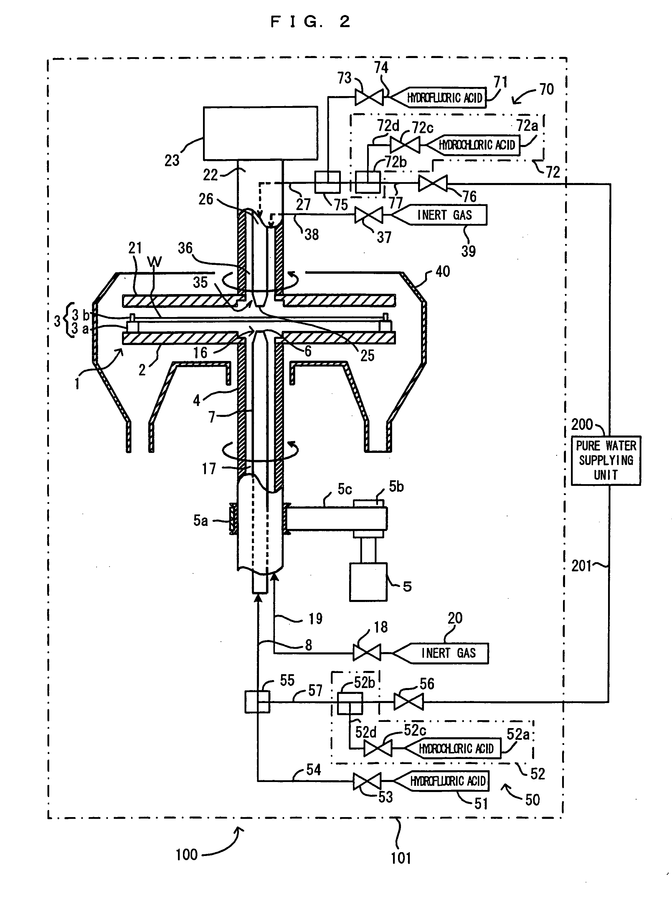
[0042]FIG. 2 is a cross sectional view of the structure of the substrate processing system as a whole according to the first embodiment of the present invention. FIG. 3 is a block diagram which shows the configuration of control of the substrate processing system shown in FIG. 2. This substrate processing system comprises a substrate processing apparatus 100 (which also corresponds to the “substrate processing unit” of the present invention) and a pure water supplying unit 200. The pure water supplying unit 200 is disposed separately from the substrate processing apparatus 100 and supplies pure water to the apparatus 100. As shown in FIG. 2, in the same processing main unit 101, the substrate processing apparatus 100 performs film removal, rinsing and drying of a substrate W which is held by a spin chuck 1. Pure water for use in the substrate processing apparatus 100 is supplied to the substrate processing apparatus 100 from the pure water supplying unit 200 via a pipe 201.

[0043] T...

second embodiment

[0063]FIG. 5 is a drawing which shows the second embodiment of the substrate processing system according to the present invention. A major difference of the second embodiment from the first embodiment is that while the first embodiment requires mixing at the mixing units 52b and 72b hydrochloric acid (diluted hydrochloric acid) directly with pure water which flows in the pipes 57 and 77 to thereby create the rinse solution, hydrochloric acid is mixed with pure water inside a storage tank 41 will be described later in the second embodiment. This structure has the following advantages. That is, the first embodiment utilizes in-line mixing of hydrochloric acid with pure water, and therefore, it is difficult to control the flow rate of hydrochloric acid and finely adjust the pH of the rinse solution. This is because adjustment of the pH of the rinse solution to a desired value necessitates controlling a small amount of hydrochloric acid. On the contrary, in the second embodiment, hydroc...

third embodiment

[0070]FIG. 6 is a drawing of the third embodiment of the substrate processing system according to the present invention. A major difference of the third embodiment from the first embodiment is that the third embodiment is directed to so-called batch processing in which a plurality of substrates W are processed at once, whereas the first embodiment is directed to so-called single water processing in which one substrate W is processed at a time. For the purpose of executing the series of substrate processing (film removal using a process solution, rinsing and drying) on a plurality of substrates W, a substrate processing apparatus of the batch type comprises a film removal bath, a rinsing bath and a drying bath. The film removal bath holds a process solution such as an etchant (hydrofluoric acid solution, etc.) and is for removal of films from the substrates. The rinsing bath holds pure water which serves as a rinse solution and is for rinsing of the substrates W. The drying bath is f...


PUM


Abstract

Nitrogen is dissolved in pure water and hydrochloric acid is mixed in this nitrogen-dissolved pure water, thereby creating as a rinsing liquid a mixture liquid whose pH is lower than that of pure water, and thus created rinsing liquid is supplied at nozzles 6 and 25 toward a substrate W. In the case of such a rinsing liquid, the dissolved oxygen concentration in the rinsing liquid is lowered, and it is possible to suppress a rapid increase of the dissolved oxygen concentration in the rinsing liquid as it is immediately after injected at the nozzles 6 and 25. Also suppressed is elution of Si from the surfaces of the substrate.

Description

CROSS REFERENCE TO RELATED APPLICATION [0001] The disclosure of Japanese Patent Applications enumerated below including specification, drawings and claims is incorporated herein by reference in its entirety: [0002] No. 2004-168304 filed Jun. 7, 2004; [0003] No. 2004-258607 filed Sep. 6, 2004; and [0004] No. 2005-113119 filed Apr. 11, 2004. BACKGROUND OF THE INVENTION [0005] 1. Field of the Invention [0006] The present invention relates to a substrate processing method, a substrate processing apparatus and a substrate processing system in which a rinse solution is supplied to a substrate, thereby rising the substrate. The substrate includes semiconductor wafers, glass substrates for photomask, glass substrates for liquid crystal display, glass substrates for plasma display, optical disk substrates and the like. [0007] 2. Description of the Related Art [0008] A method of manufacturing electronic components for semiconductor devices, liquid crystal display devices and the like include ...

Claims


Application Information

Patent Timeline
IPC IPC(8): C11D3/00C11D17/04H01L21/00
CPCC11D17/041H01L21/6708H01L21/67086
Inventor MIYA, KATSUHIKOIZUMI, AKIRAKISHIMOTO, TAKUYA
Owner DAINIPPON SCREEN MTG CO LTD
Why Eureka
Try Eureka