
Fluid-channel device with covalently bound hard and soft structural components

a fluid channel and structural component technology, applied in the field of analytical chemistry, can solve the problems of glue being a potential source of chemical contamination, glue being subject to failure, and the additional component of the clamp must be adjusted and adjusted, so as to reduce the risk of contamination of free-moving adhesive components

Inactive Publication Date: 2005-12-15
AGILENT TECH INC
View PDF8 Cites 22 Cited by
  • Summary
  • Abstract
  • Description
  • Claims
  • Application Information

AI Technical Summary

Benefits of technology

The present invention provides a method for bonding a polymer fluid-channel substrate with another component to form a fluid-channel device. The surfaces of the substrate and the other component are pretreated to create complementary surfaces, which can then be joined together through a covalent bond. The bond can be formed between amino groups on the substrate and amino-complement groups on the other component. The invention also allows for the creation of fluid channels before, during, or after the bonding process. The bonding surfaces can be thermoplastic, and the invention provides for devices that can analyze fluids or use them for some purpose. The invention also allows for the creation of fluid-channel devices with built-in electronic circuitry. The covalent bonds are strong and the risk of contamination from adhesive components is reduced. The molecular segments between the surfaces provide some degree of elasticity to accommodate differential thermal expansion without slippage.

Problems solved by technology

An external clamp can be used to hold a “sandwich” together, but the clamp then represents an additional component that must be adjusted and is subject to failure.
An adhesive can be used to “glue” the hard and soft devices together, but like an external clamp, the glue is another component subject to failure.
In addition, the glue is a potential source of chemical contamination.
Also, the glue can impair transparency where optical access is required.
However, the temperatures involved in fusing can degrade preformed microchannels or associated heat-sensitive components.
Also, if the components have different thermal coefficients of expansion, differential contraction after fusing can cause a component to break or leave undesirable stresses in the completed structure.
Also, many soft materials of interest, e.g., many polyimides, are not thermoplastics—so this approach to attachment is not applicable.
These techniques also make it hard to fabricate devices where the hard layer is patterned beforehand.

Method used


Image

  • Fluid-channel device with covalently bound hard and soft structural components
  • Fluid-channel device with covalently bound hard and soft structural components
  • Fluid-channel device with covalently bound hard and soft structural components

Examples


Embodiment Construction

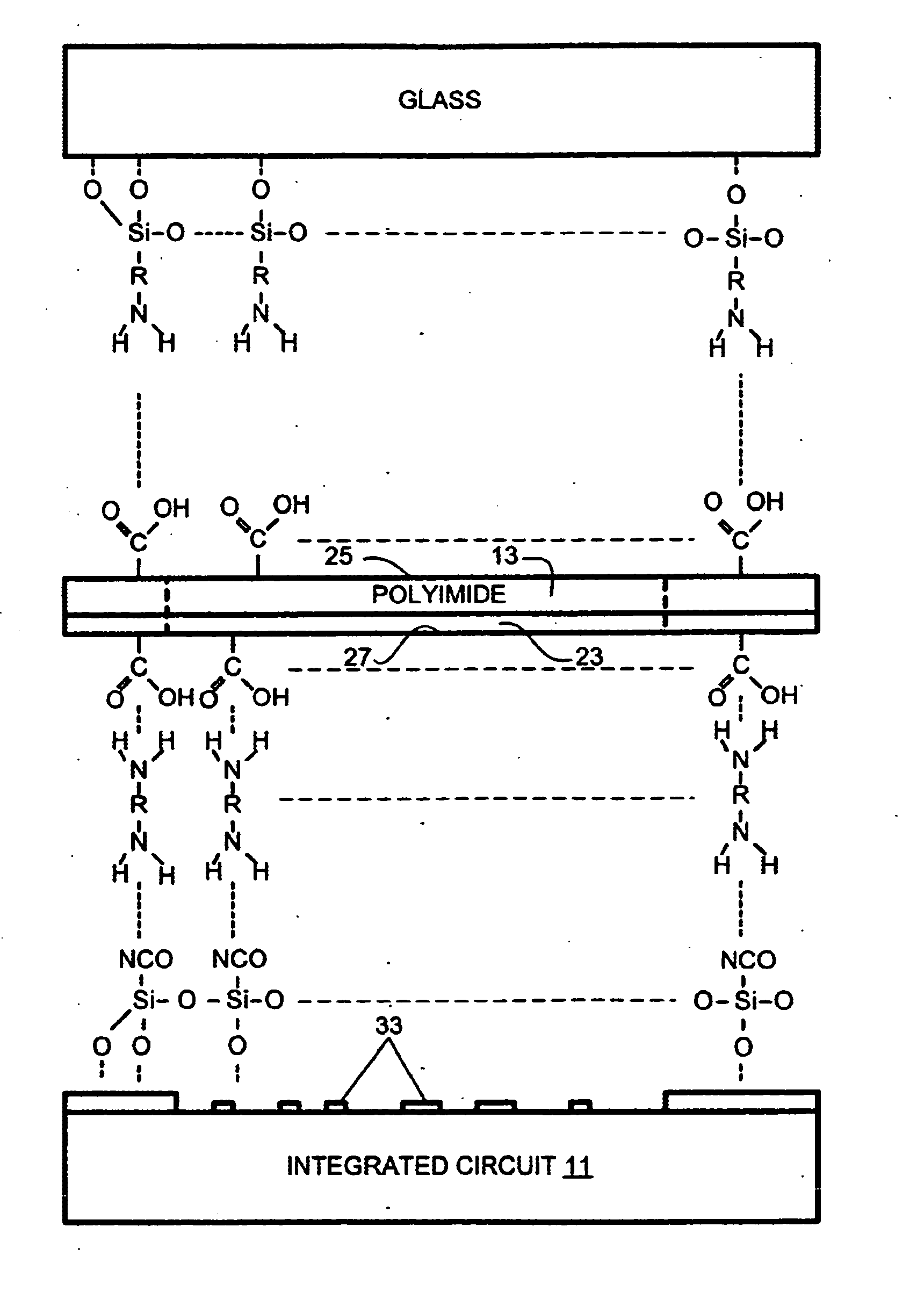
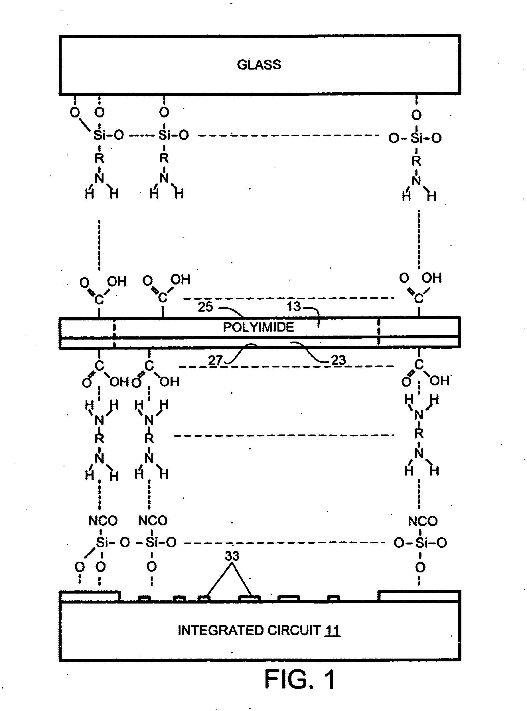
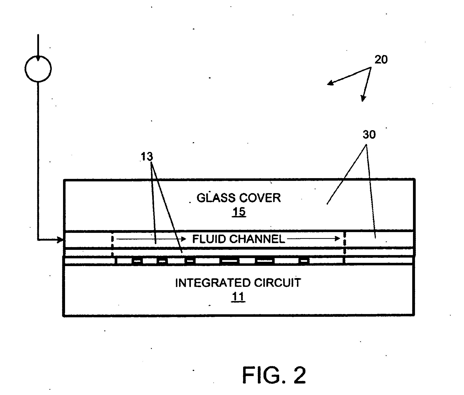
[0017] The invention provides for covalently bonding an integrated circuit 11 and a glass cover 13 to a polyimide intermediate structure 15 as shown in FIG. 1. This process occurs in the context of the manufacture of a microfluidic device 20, shown in FIG. 2 in accordance with a method M1 flow charted in FIG. 3. The polyimide structure 15 has a relatively thick, 5 mil, non-thermoplastic (Kapton H) layer 21 and a relatively thin, 1-micron, thermoplastic coating 23 on one side.

[0018] At step S1, glass cover 13, precleaned using standard (e.g., RCA) procedures, is chemically modified with aminopropyl trimethoxysilane to render an amine-rich surface (FIG. 1). At step S2, polyimide structure 15 is activated by dipping in potassium hydroxide solution (1M, room temp, 1 h); this is followed by HCl solution (ca 0.2M) to displace the salt ions, exposing carboxyl groups at the uncoated polyimide surface 25. Note that steps S1 and S2 can be performed concurrently or in any order.

[0019] At ste...


PUM

PropertyMeasurementUnit
thickaaaaaaaaaa
pressureaaaaaaaaaa
pHaaaaaaaaaa

Abstract

A hybrid hard / soft microfluidic device is assembled by covalently bonding bard and soft materials. The channels are formed in a polyimide material, which is to be sandwiched between an integrated circuit and a glass cover. The glass covered is treated with an amino siloxane to form free amine groups. The polyimide is treated to form free carboxyl groups. The glass and polyimide are bonded through amidation. The remaining polyimide surface is treated with polyamines to form free amine groups, while silicon dioxide surfaces of the integrated surface are treated with isocyanate siloxane to form free isocyanate groups. The integrated circuit is then covalently bonded to the polyimide surface. The latter surface can be a thermoplastic coating that offers some compliance, more intimate contact, and more thorough bonding.

Description

BACKGROUND OF THE INVENTION [0001] The present invention relates to analytical chemistry and, more particularly, to the manufacture of fluid-channel devices such as microfluidic devices used in analytical chemistry. A major objective of the present invention is to provide for securely bonded hybrid hard / soft microfluidic devices. [0002] Advances in the medical, chemical, environmental, and forensic sciences have been made possible by advances in the equipment used for analyzing chemical samples. Among the most important types of analytical equipment are devices that separate chemical components according to their migration rates along a channel. Such separation technologies including chromatography, in which the rate of motion of a chemical component through a channel is determined by its partitioning between mobile and stationary phases. In general, narrow bore devices provide higher separation resolution by minimizing non-longitudinal motion through the channel. While large-bore c...

Claims


Application Information

Patent Timeline
Patent Type & Authority Applications(United States)
IPC IPC(8): B01L3/00B32B37/00
CPCB01L3/5027B32B37/00B32B38/06B32B2315/08B32B2379/08
Inventor ROITMAN, DANIEL B.ROBOTTI, KARLA M.KILLEEN, KEVIN P.
Owner AGILENT TECH INC
Learn More