
Method and device for controlling device

a technology of controlling device and control device, which is applied in the direction of motor/generator/converter stopper, dynamo-electric converter control, tractors, etc., can solve the problems of inability to compensate for the influence of disturbance applied to the tires, deterioration of the road holding properties of tires, and inability to say, so as to reduce the change level of road holding force and facilitate control

Inactive Publication Date: 2005-12-15
BRIDGESTONE CORP
View PDF10 Cites 50 Cited by
  • Summary
  • Abstract
  • Description
  • Claims
  • Application Information

AI Technical Summary

Benefits of technology

[0018] The inventors of the present invention have conducted intensive studies and have found that the running state of a car can be stabilized by extracting a change in wheel speed or car body drive force and suppressing the extracted change in wheel speed or car body drive force. The present invention has been accomplished based on this finding. Stated more specifically, a change in the attitude of the car body or car speed included in any one of wheel speed detected by a wheel sensor and car body drive force for moving forward the car body generated on the tire contact surface and obtained from drive force and wheel torque applied to each drive wheel and further fluctuating components caused by the disturbance of each tire are separated and extracted to be fed back to the target drive force directly, or drive force or braking force to be applied to the drive wheel is controlled according to these fluctuating components, and further vibration is applied to the tire to suppress the deformation of the tire caused by the above tire disturbance, thereby suppressing vibration caused by a change in drive force or the above disturbance. Thus, stable car control becomes possible.

Problems solved by technology

However, since the influence of disturbance (micro-vibration) applied to the tires caused by fluctuations in the contact pressure of the tires due to changes in the condition of the road and changes in the vibration of unsprung mass including the suspension and having a cycle of 100 msec or less cannot be compensated for by the general control of the above engine-drive car, the road holding properties of the tires deteriorate.
Meanwhile, in the electric car, although shorter cyclic control than that of the engine-drive car is possible, a higher frequency band fluctuating component than the response frequency of the car body included in the above detected motor torque and wheel speed cannot be specified, thereby making it impossible to compensate for the influence of disturbance applied to the tires.
Since only the friction force of the tires is controlled in the method in which micro-vibration is directly applied to the tires, it cannot be said that the control of the attitude of the car and the car speed is satisfactory.
Thus, satisfactory car control is impossible.

Method used


Image

  • Method and device for controlling device
  • Method and device for controlling device
  • Method and device for controlling device

Examples


example 1

[0119] To verify the effect of the present invention, a two-wheel independently controlling electric car is used as a test car to carry out a turning and running test so as to measure its critical turning speed. The friction coefficient of the test road was 0.4, and the radius of turning was 30 m. The car kept turning by increasing its car speed and the speed when the amount of steering exceeded a threshold value was taken as a critical speed. The test car was apt to be over-steered at a critical range. Therefore, when the car turned to the left, the steering angle indicator swung to the right so as to suppress spinning at the critical range. The speed when the steering angle indicator swung to the right was taken as the above critical speed.

[0120] Table 1 below shows the comparison of the critical speed between the control (no control) of the prior art and the control of the present invention. Control (1) means that tire disturbance compensation was made and control (2) means that...

example 2

[0125] Control for suppressing a fluctuating component of the wheel torque as shown in Table 3 above was made on the test car based on only information on wheel speed and the test car was caused to run on a dry asphalt road to compare its driving stability with that of the control (no control) of the prior art. The results are shown in Table 4 below.

TABLE 4EXISTENCE OF CONTROLEVALUATIONABSENCE+6EXISTENCE+7

[0126] As obvious from Table 4, even when the running state of the car was controlled based on only information on wheel speed, it was confirmed that the results of sensor evaluation by the existence of control are superior to those of the prior art.


PUM


Abstract

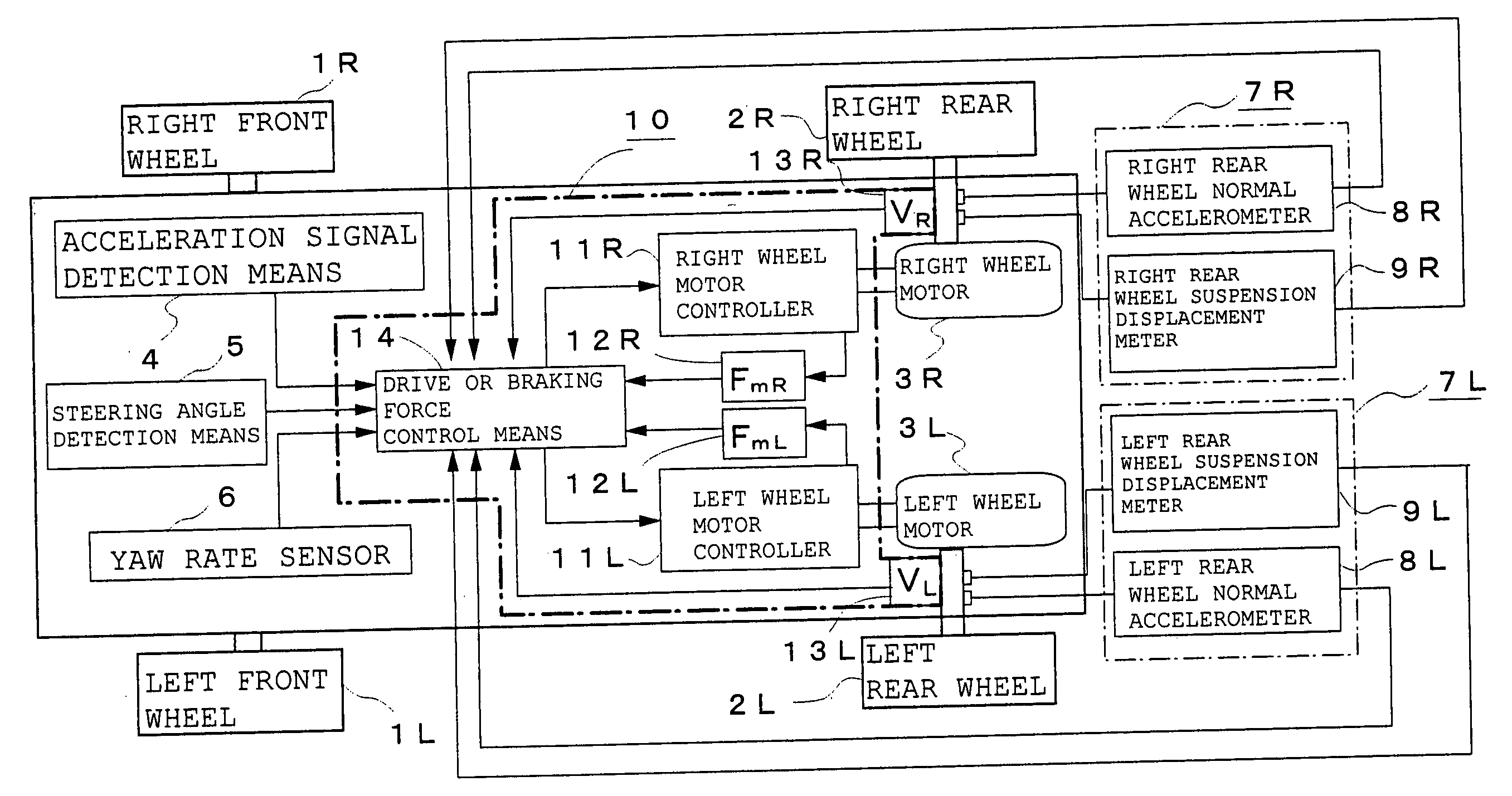
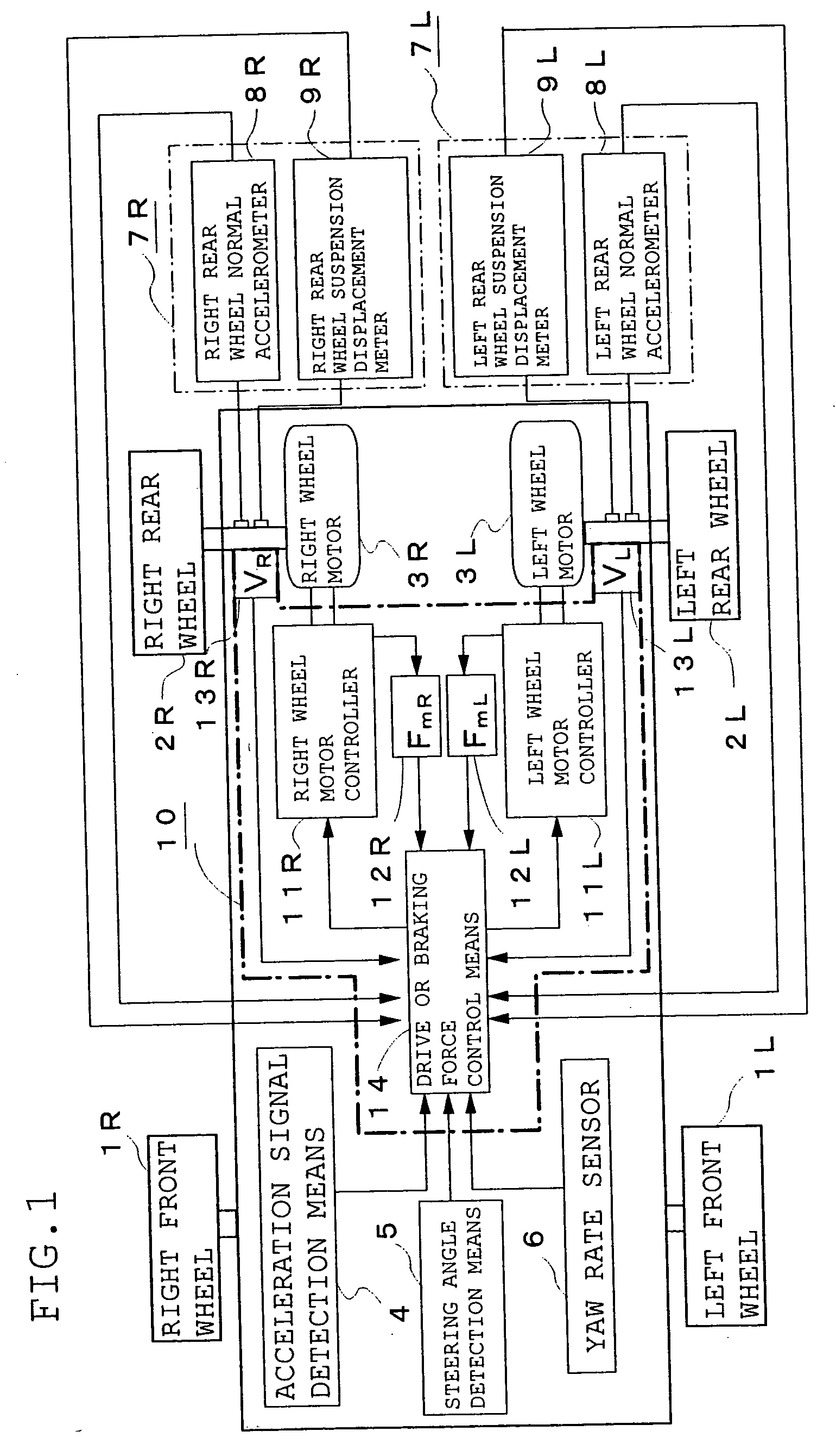
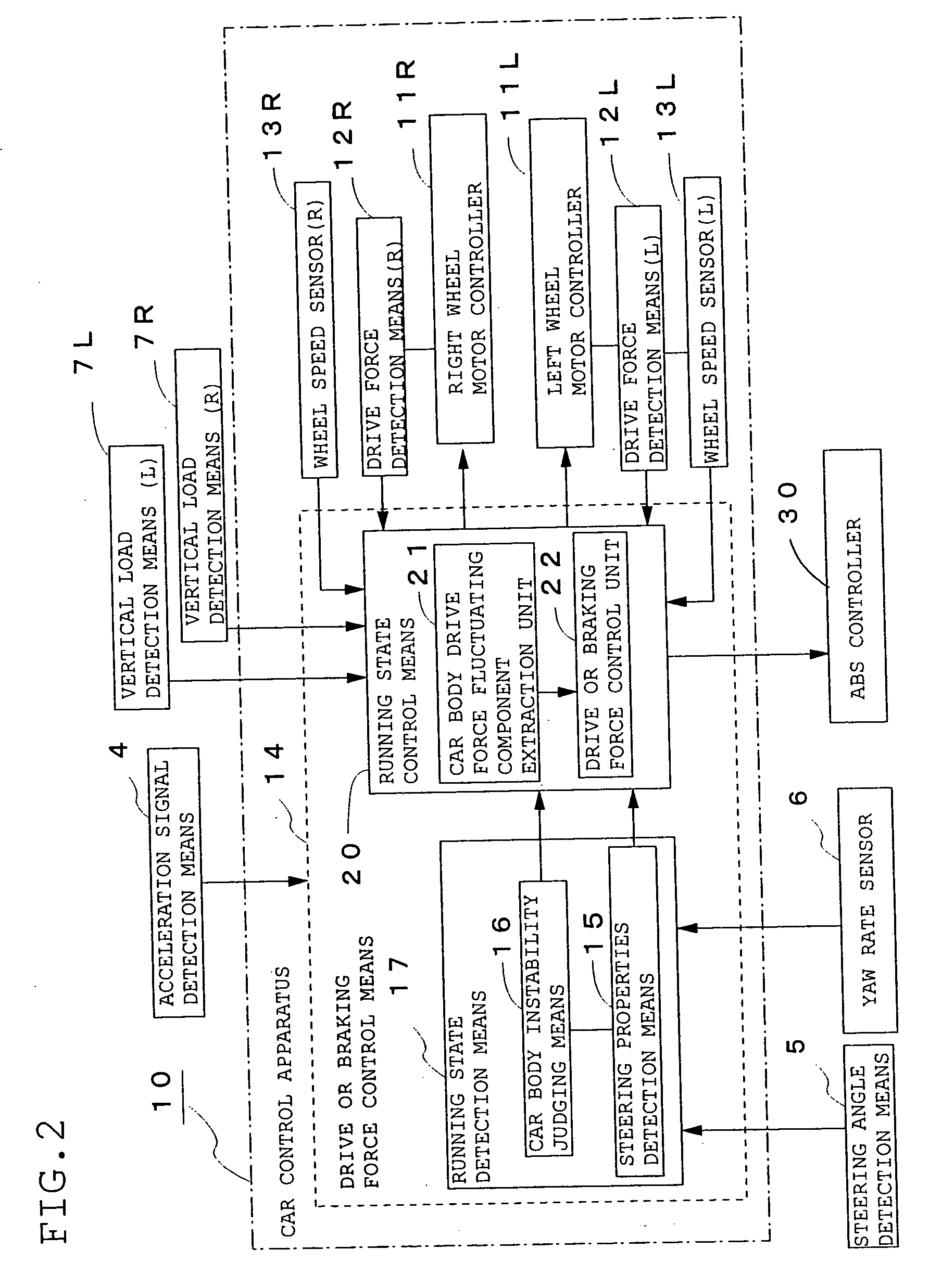
A car control apparatus comprising a wheel sensor 13, wheel torque calculating means 23 for calculating wheel torque from the wheel speed, drive force detecting means 12 for detecting drive force generated by an electric motor 3, car body drive force calculating means 24 for calculating car body drive force from the above drive force and wheel torque, car body drive force fluctuating component extracting means 25 for extracting multiple frequency band fluctuating components of the car body drive force, and drive or braking force control unit 22 for controlling the running state of a car, wherein drive or braking force to be applied to each wheel is obtained from main drive force, slip ratio control drive force and tire disturbance compensation drive force calculated based on the extracted fluctuating components of the car body drive force and supplied to a motor controller 11 to drive or brake the drive wheel 2 and apply micro-vibration to the tire in order to suppress micro-vibration generated between the tire and the road surface, thereby making it possible to improve the road holding properties of the tire and the driving stability of the car by compensating for disturbance applied to the tire.

Description

BACKGROUND OF THE INVENTION [0001] 1. Field of the Invention [0002] The present invention relates to a car control method and, specifically, to a car control method for suitably controlling drive or braking force applied to wheels and suppressing disturbance applied to tires and an apparatus for use in the method. [0003] 2. Description of the Prior Art [0004] In the prior art, to control the running state of a car by controlling drive force applied to drive wheels, in the case of an engine-drive car, the target engine speed is calculated based on the input acceleration signal, and the opening of a throttle valve is controlled to adjust the engine speed so that the actual car speed detected by a car speed sensor becomes a car speed calculated from the above target engine speed so as to control drive torque applied to an output shaft connected to the drive wheels. [0005] In an electric car in which drive wheels are driven or braked by an electric motor, as shown in the control flow of...

Claims


Application Information

Patent Timeline
Patent Type & Authority Applications(United States)
IPC IPC(8): B60L3/10B60L15/20
CPCB60L3/102B60L15/2045Y02T10/645Y02T10/7283B60L15/20B60L2220/46Y02T10/64Y02T10/72
Inventor WAKAO, YASUMICHIAKUTAGAWA, KEIZO
Owner BRIDGESTONE CORP
Learn More