Motor driving device, motor driving method, and electronic device

a technology of motor driving and driving method, which is applied in the direction of motor/generator/converter stopper, electric controller, dynamo-electric converter control, etc., can solve the problems of power consumption increase, the phase of the position signal is sometimes shifted, and the driving efficiency of the motor becomes low, so as to achieve low cost, high efficiency, and small size

Inactive Publication Date: 2005-12-15
PANASONIC CORP
View PDF2 Cites 27 Cited by
  • Summary
  • Abstract
  • Description
  • Claims
  • Application Information

AI Technical Summary

Benefits of technology

[0032] An electronic apparatus in one aspect of the present invention has the above-mentioned motor driving device. The present invention can realize an electronic apparatus that is small in size a...

Problems solved by technology

However, the phase of the position signal is sometimes shifted due to various factors, such as rotation number and load torque of the motor.
Thereby, the electrification phase is shifted, the driving efficiency of the motor becomes low, and the power consumption increases.
Moreover, when the motor is driven with the voltage having a rectangular waveform based on rotor position information which is obtained a few times per one rotation of motor, the motor vibrates and noise is generated during the rotation of the motor.
However, the motor driving devices for controlling relativel...

Method used


Image

  • Motor driving device, motor driving method, and electronic device
  • Motor driving device, motor driving method, and electronic device
  • Motor driving device, motor driving method, and electronic device

Examples


Embodiment Construction

[0051] Embodiment specifically exemplifying the best mode for carrying out the present invention will be described below referring to the accompanying drawings.

>

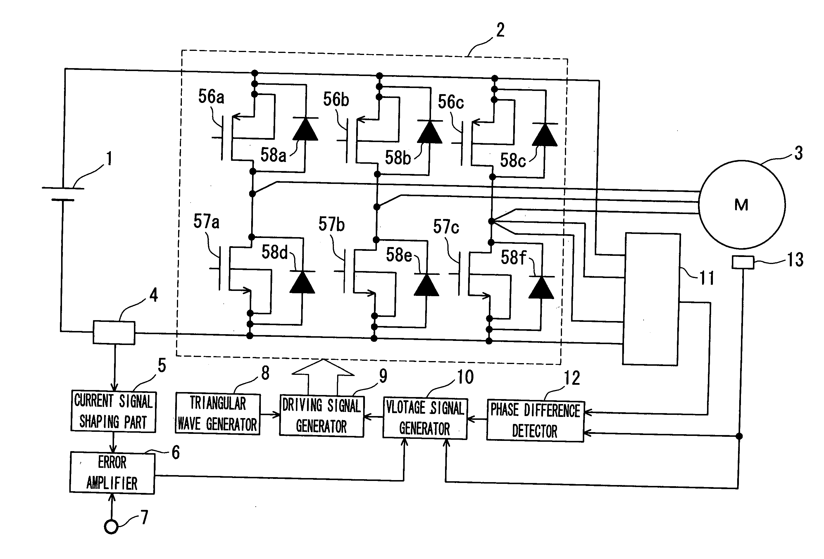
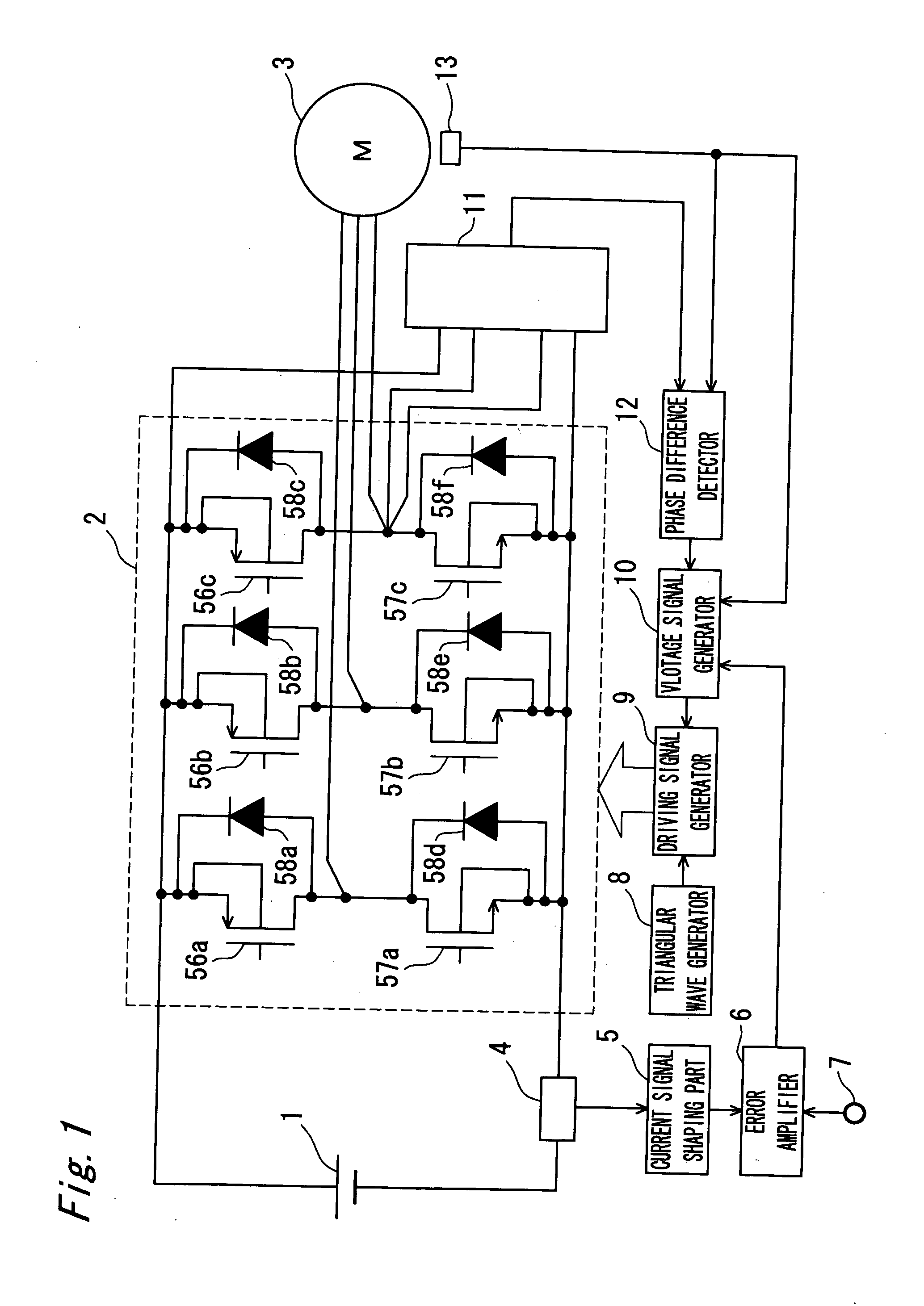
[0052] Referring to FIGS. 1 through 13, a motor driving device and a motor driving method in accordance with Embodiment of the present invention will be described below. FIG. 1 is a block diagram showing a configuration of a motor driving device in accordance with Embodiment of the present invention.

[0053] A motor driving device in accordance with Embodiment of the present invention is a motor driving device for a spindle motor of an optical disk device.

[0054] A direct current power source 1 supplies power to the motor driving device. A current detector 4 detects a source current flowing in a motor driving part 2. A current signal shaping part 5 generates a current signal depending on a peak value of the source current detected by the current detector 4. An error amplifier 6 inputs the current signal that is output by the...


PUM


Abstract

A motor driving device that is low in cost and capable to control the phase of a motor with high efficiency and with accuracy. A motor driving device includes a motor driving part, a rotor position detector, a current phase detector, a voltage signal generator, and a driving signal generator. The motor driving part has a plurality of half bridge circuits in which a high potential side drive transistor and a low potential side drive transistor are connected in series to each other, and a connection point therebetween serves as a stator winding driving terminal of each phase of a motor. The rotor position detector detects a rotor position of the motor and outputting a rotor position signal. The current phase detector detects the phase of a phase current flowing in the stator winding driving terminal. The voltage signal generator controls and generates a voltage profile signal such that a first phase difference that is a difference between the phase of the phase current and the phase of the rotor position signal is kept to a predetermined electrical angle. The driving signal generator generates a PWM signal that drives the drive transistor of each phase depending on the voltage profile signal.

Description

BACKGROUND OF THE INVENTION [0001] The present invention generally relates to a motor driving device, a motor driving method, and an electronic device having the motor driving device. [0002] A brushless motor driving device detects a rotor position of a motor to be controlled, and sends a current to a stator winding according to the position signal. However, the phase of the position signal is sometimes shifted due to various factors, such as rotation number and load torque of the motor. Thereby, the electrification phase is shifted, the driving efficiency of the motor becomes low, and the power consumption increases. Moreover, when the motor is driven with the voltage having a rectangular waveform based on rotor position information which is obtained a few times per one rotation of motor, the motor vibrates and noise is generated during the rotation of the motor. [0003] Japanese Unexamined Patent Publication 2001-037279 discloses motor driving devices of the first and second prior ...

Claims


Application Information

Patent Timeline
IPC IPC(8): H02P7/06
CPCH02P23/0004H02P23/26
Inventor YAMAMOTO, YASUNORIMORI, HIDEAKIIGARASHI, YOSHIAKI
Owner PANASONIC CORP
Why Eureka
Try Eureka