Method and apparatus for visual detection and inspection of objects

a visual detection and object technology, applied in the field of automatic detection and inspection of objects, can solve the problems of inability to know in advance which active frames will contain this evidence, inability to adjust the weighted average pass score, and unstable motion of the obj

Active Publication Date: 2005-12-15
COGNEX TECH & INVESTMENT
View PDF99 Cites 105 Cited by
  • Summary
  • Abstract
  • Description
  • Claims
  • Application Information

AI Technical Summary

Benefits of technology

[0064] Another aspect of the invention is a method for producing output signals that are synchronized to a time, shaft encoder count, or other event marker that indicates when an object has crossed a fixed reference po...

Problems solved by technology

In this scenario, there is no way to know in advance which of the active frames will contain this evidence.
Thus, weighted average pass score is not appropriate in this case.
An alternative is to pass the object if the pass score exceeds some threshold in any of the active frames, but this alternative may pass objects on the basis of too little evidence.
If a Photo is linked to two nearly parallel Locators, its motion would be unstable.
The result combines the capabilities of a vision detector with those of a PLC, resulting in a powerful industrial inspection machine but at a cost of increased complexity.
For example, a vision detector may not be able to measure or use object speed in an indexed application.
Furthermore, the delay may be quite variable, depending on how many frames were analyzed and, to a lesser extent, when in the acquire/process cycle the mark tim...

Method used


Image

  • Method and apparatus for visual detection and inspection of objects
  • Method and apparatus for visual detection and inspection of objects
  • Method and apparatus for visual detection and inspection of objects

Examples


Embodiment Construction

Discussion of Prior Art

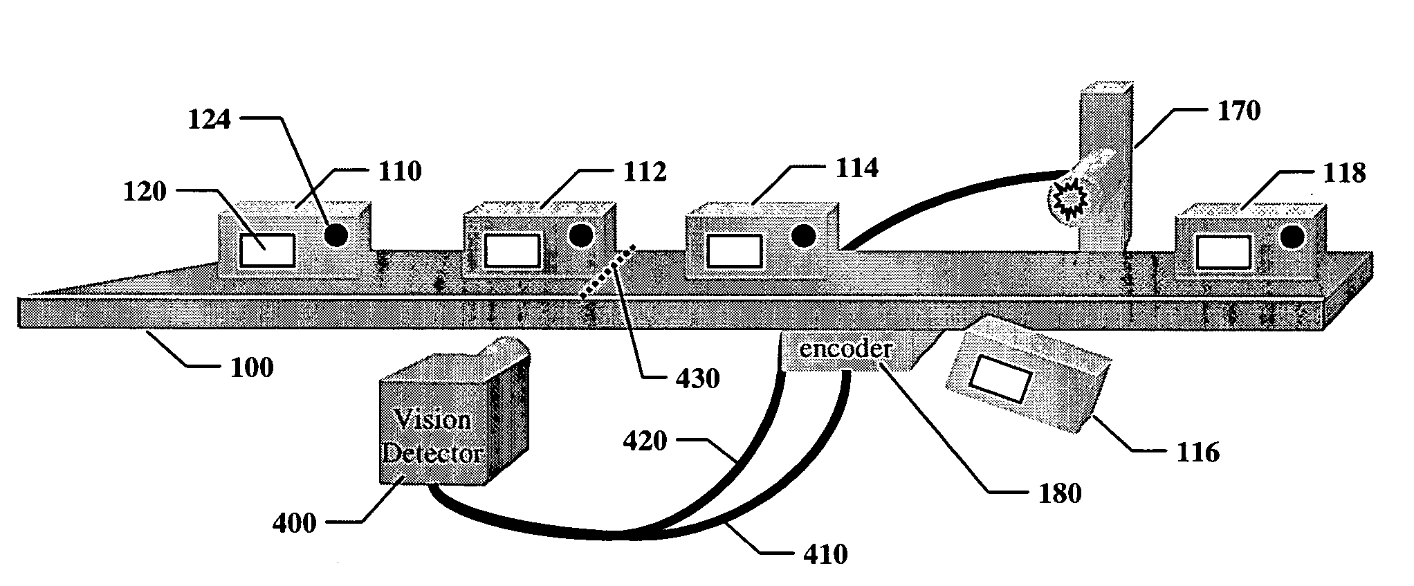
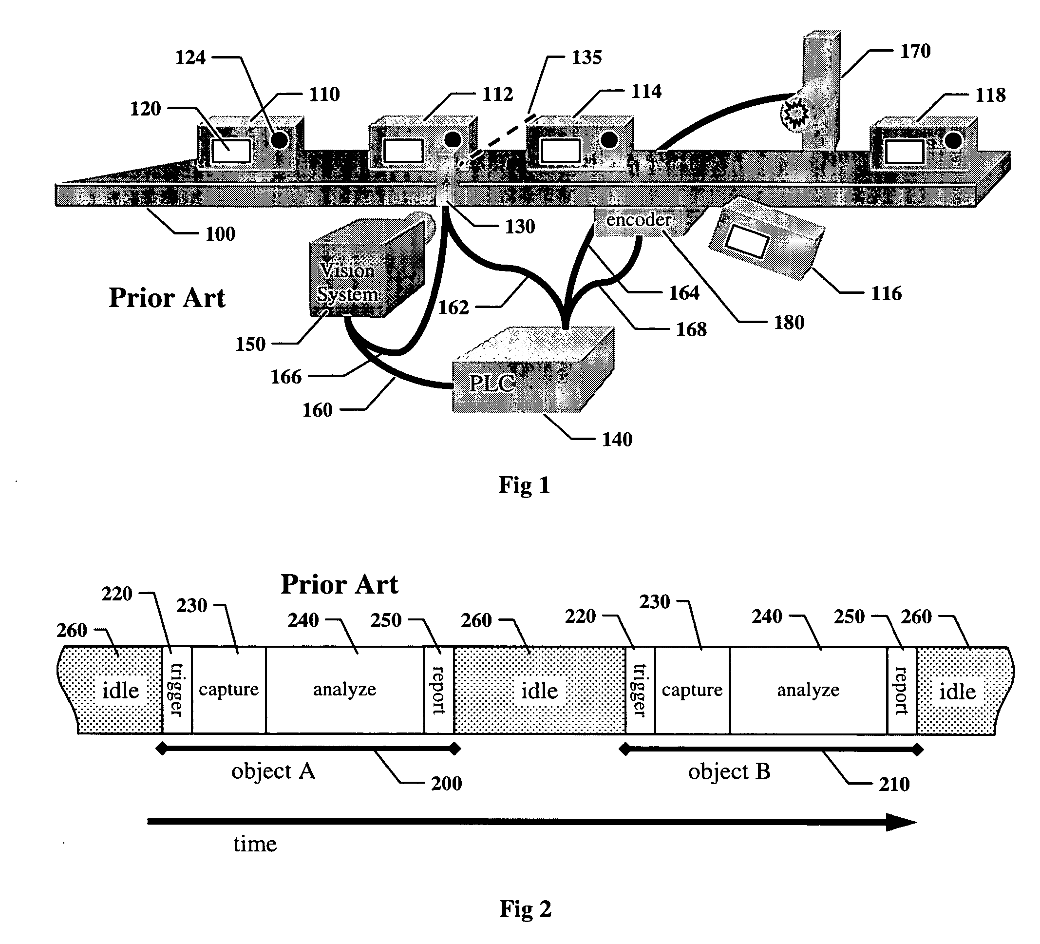
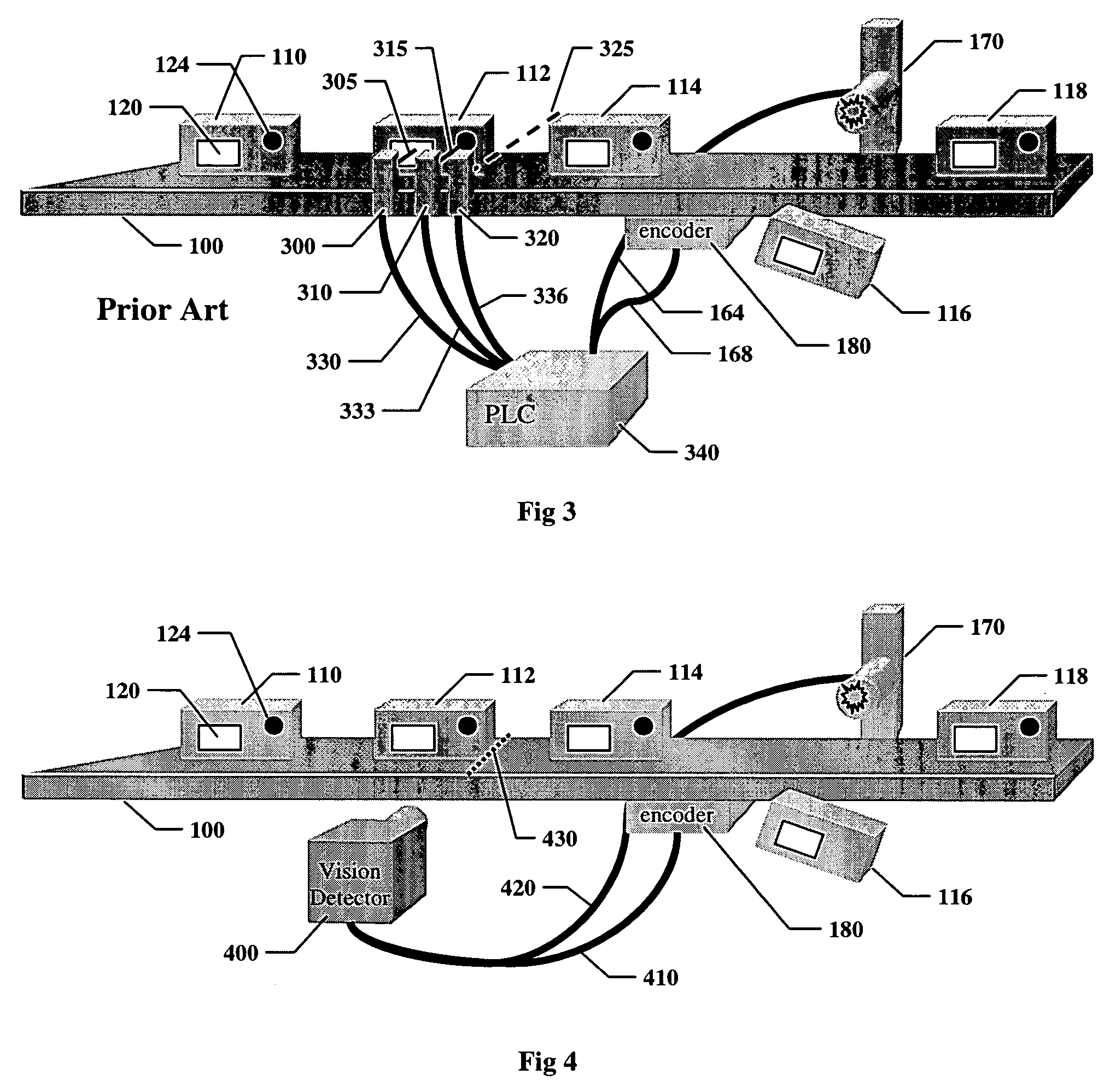
[0114]FIG. 1 shows a prior art machine vision system used to inspect objects on a production line. Objects 110, 112, 114, 116, and 118 move left to right on a conveyer 100. Each object is expected to contain certain features, for example a label 120 and a hole 124. Objects incorrectly manufactured may be missing one or more features, or may have unintended features; for example, object 116 is missing the hole. On many production lines motion of the conveyer is tracked by a shaft encoder 180, which sends a signal 168 to a programmable logic controller (PLC) 140.

[0115] The objects move past a photodetector 130, which emits a beam of light 135 for detecting the presence of an object. Trigger signals 162 and 166 are sent from the photodetector to the PLC 140, and a machine vision system 150. On the leading edge of the trigger signal 166 the vision system 150 captures an image of the object, inspects the image to determine if the expected features are present, a...


PUM


Abstract

Disclosed are methods and apparatus for automatic optoelectronic detection and inspection of objects, based on capturing digital images of a two-dimensional field of view in which an object to be detected or inspected may be located, analyzing the images, and making and reporting decisions on the status of the object. Decisions are based on evidence obtained from a plurality of images for which the object is located in the field of view, generally corresponding to a plurality of viewing perspectives. Evidence that an object is located in the field of view is used for detection, and evidence that the object satisfies appropriate inspection criteria is used for inspection. Methods and apparatus are disclosed for capturing and analyzing images at high speed so that multiple viewing perspectives can be obtained for objects in continuous motion.

Description

BACKGROUND OF THE INVENTION [0001] 1. Field of the Invention [0002] The invention relates to automated detection and inspection of objects being manufactured on a production line, and more particularly to the related fields of industrial machine vision and automated image analysis. [0003] 2. Description of the Related Art [0004] Industrial manufacturing relies on automatic inspection of objects being manufactured. One form of automatic inspection that has been in common use for decades is based on optoelectronic technologies that use electromagnetic energy, usually infrared or visible light, photoelectric sensors, and some form of electronic decision making. [0005] One well-known form of optoelectronic automatic inspection uses an arrangement of photodetectors. A typical photodetector has a light source and a single photoelectric sensor that responds to the intensity of light that is reflected by a point on the surface of an object, or transmitted along a path that an object may cro...

Claims


Application Information

Patent Timeline
IPC IPC(8): G01B11/24G01N21/00G01N21/89G06K9/46G06T7/00G06T7/20
CPCG01N2021/8909G06K9/4609G06T7/0004G06T7/0002G06T7/0042G06T7/20G06T2207/30164G06T7/0006G06T7/73G06V10/443
Inventor SILVER, WILLIAM M.
Owner COGNEX TECH & INVESTMENT
Why Eureka
Try Eureka