Method and apparatus for protecting an EUV reticle from particles

a technology of reticle and euv, which is applied in the direction of photomechanical equipment, instruments, printing, etc., can solve the problems of euv lithography that does not use pellicles to protect euv reticles from particle contamination, pellicles are not used to protect euv reticles, and the lithography process which utilizes reticles may be compromised, so as to reduce particle contamination

Inactive Publication Date: 2005-12-15
NIKON CORP
View PDF6 Cites 52 Cited by
  • Summary
  • Abstract
  • Description
  • Claims
  • Application Information

AI Technical Summary

Benefits of technology

[0010] A reticle shield effectively masks off much of the surface of a reticle and includes an opening which defines an illumination area that may be illuminated by a beam or beams of EUV radiation. When such a reticle shield is used in conjunction with a magnetic field, e.g., a static magnetic field, the likelihood of particles coming into contact with the surface of the reticle is reduced. Particles which pass through the beams of EUV radiation are typically charged, and subsequently deflected away from the opening in the reticle shield and, hence, the surface of the reticle, by the magnetic field. Hence, the number of particles which may pass through the opening is relatively low. To further decrease the number of particles which may pass through the openings, an extension of the reticle shield may be built up around the opening. When the extension is shaped to conform to the profile of the beams of EUV radiation without touching the beams, fewer potential particle trajectories which may result in a particle reaching the surface of the reticle are possible.
[0011] According to another aspect of the present invention, a lithographic system includes an object holder, an illumination source, a shield, and a magnetic arrangement. The object holder supports an object having a front surface that is to be protected from particles, while the illumination source is arranged to supply a beam which is capable of providing the particles with charges. The shield, which is positioned in proximity to the object holder, has an opening defined therethrough through which the beam may pass to substantially illuminate an area of the object that is arranged to be supported by the object holder. Finally, the magnetic arrangement provides a magnetic field to deflect the charged particles away from the opening defined in the shield. The magnetic field and the shield cooperate to substantially protect the object from being contaminated by the charged particles. In one embodiment, the beam is a beam of EUV radiation.
[0012] In accordance with still another aspect of the present invention, a method for reducing particle contamination on a surface of an object includes providing a shield with an opening defined therein in proximity to the surface of the object, as well as providing a beam through the opening defined in the shield. The beam substantially illuminates an area of the surface, and also generally charges particles which pass through the beam. The method also includes creating a first magnetic field that is arranged to substantially encompass the opening and a portion of the beam near the shield, and deflecting the charged particles away from the opening using the first magnetic field.

Problems solved by technology

When a pattern is distorted, as for example due to particle contamination on a surface of a reticle, a lithography process which utilizes the reticle may be compromised.
Pellicles, however, are not used to protect EUV reticles, since thin films generally are not suitable for providing protection in the presence of EUV radiation.
Since thermophoresis may not be used in a high vacuum environment, while thermophoresis is effective in protecting reticles from particle contamination in some applications, thermophoresis may not be suitable for use in EUV lithography to protect EUV reticles from particle contamination.
The use of an electric field, however, while suitable for deflecting particles from a surface of an EUV reticle, may not be practical in some situations.
For example, the need for a power supply to provide the electric field may be problematic.
In addition, any stray electric field lines which intersect the reticle surface may actually drive charged particles onto the reticle.
The use of an electric field alone typically will not prevent the deposition of particles whose trajectory does not intercept the region of EUV radiation on the reticle, as such particles will generally not become charged.

Method used


Image

  • Method and apparatus for protecting an EUV reticle from particles
  • Method and apparatus for protecting an EUV reticle from particles
  • Method and apparatus for protecting an EUV reticle from particles

Examples


Embodiment Construction

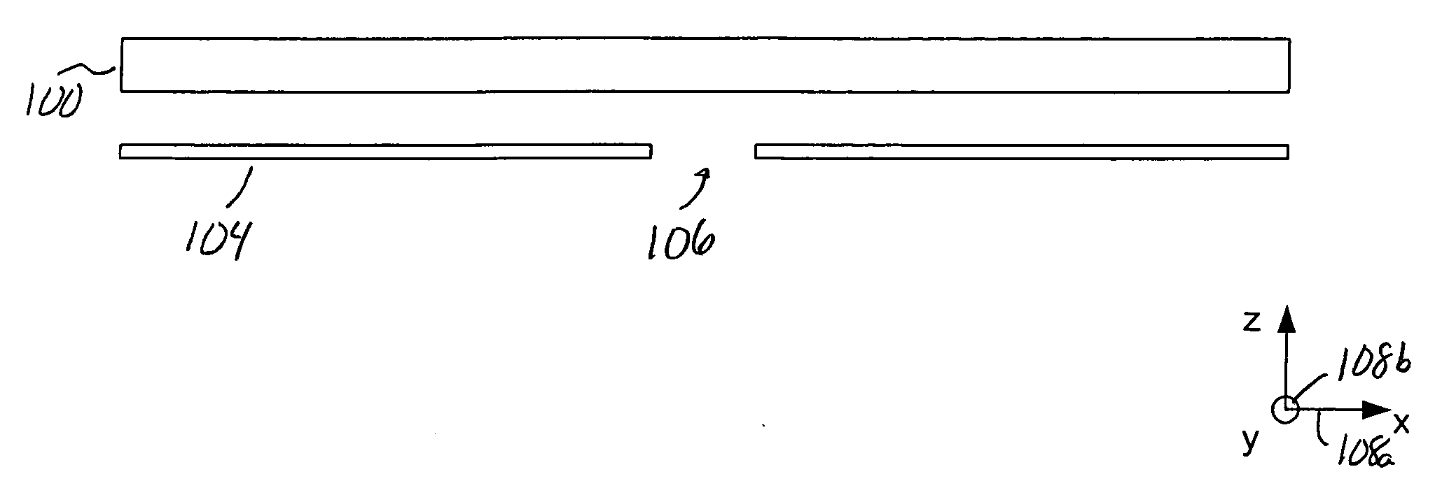
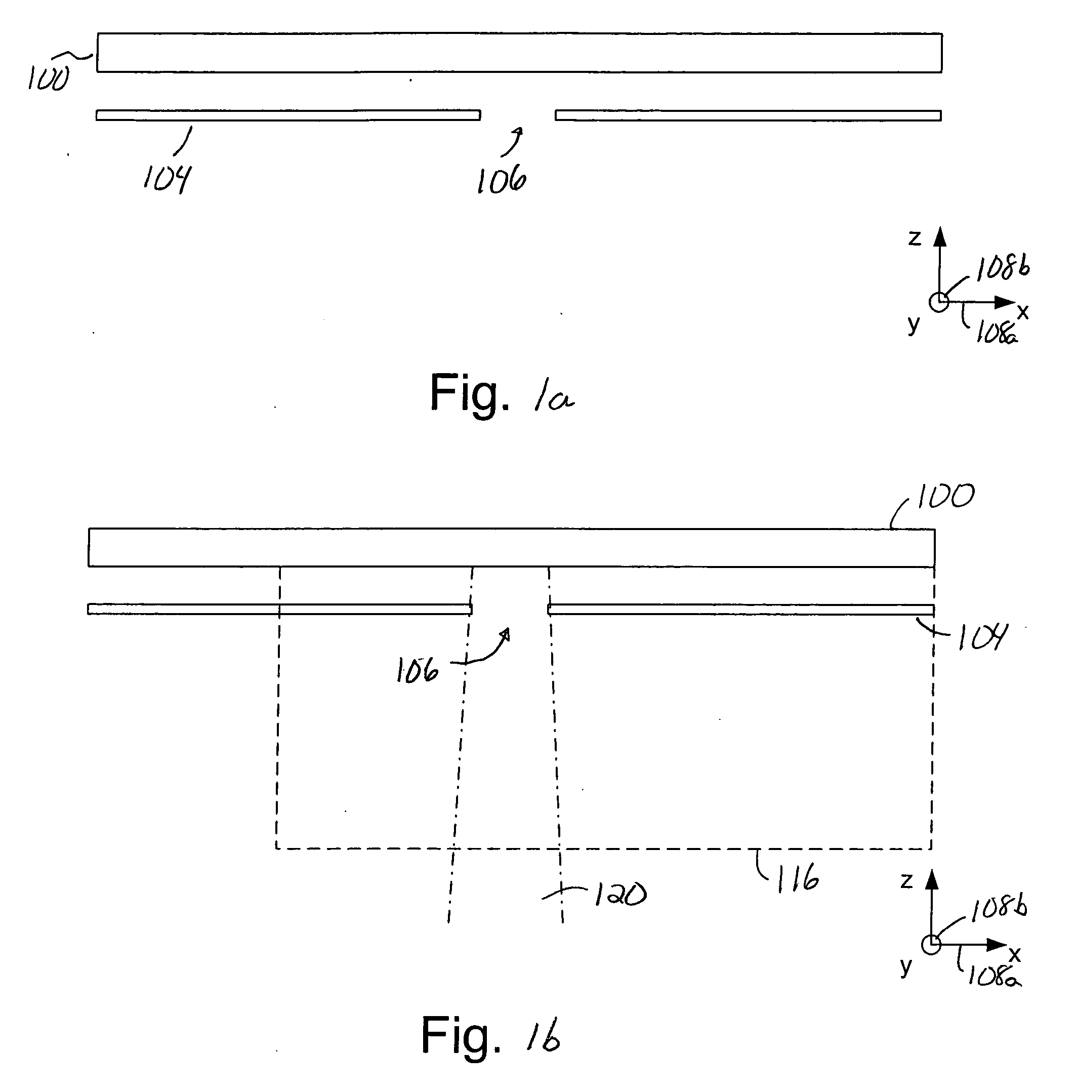
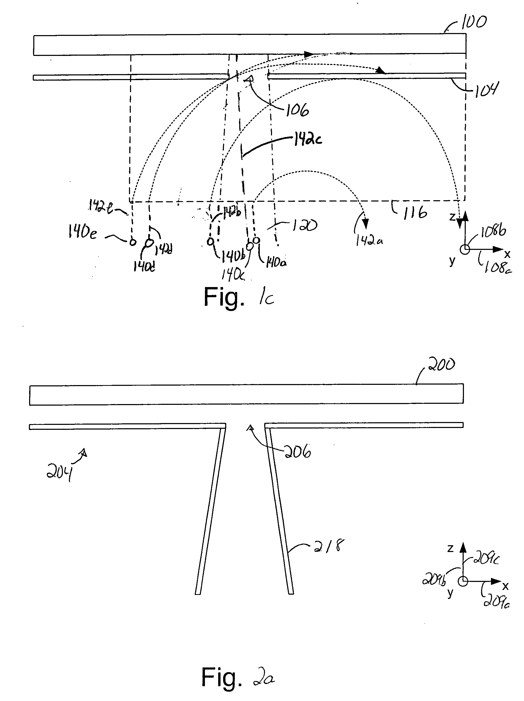
[0041] Particle contamination on critical surfaces of reticles such as reticles used in extreme ultraviolet (EUV) lithography systems may compromise the integrity of semiconductors created using the reticles. Hence, protecting critical surfaces of reticles from contaminants is important to ensure the integrity of lithography processes. Some reticles are protected from particles through the use of pellicles. However, pellicles are not suitable for use in protecting surfaces of EUV reticles. While thermophoresis is also often effective in protecting reticle surfaces from particle contamination, since the use of thermophoresis as a method of protection from particle contamination is not suitable in a relatively high vacuum, EUV reticles may not be protected from particle contamination through the use of thermophoresis.

[0042] By protecting substantially all of a front surface of a reticle, with the exception of the area of the reticle that is to be illuminated using EUV beams, using a ...


PUM


Abstract

Methods and apparatus for reducing particle contamination on a reticle used in an extreme ultraviolet (EUV) lithography process. According to one aspect of the present invention, an apparatus that protects a surface of an object includes a plate that is positioned in proximity to the surface and protects at least a first portion of the surface. An opening is defined within the plate, and is such that a second portion of the surface is exposed through the opening. The apparatus also includes at least one magnetic component which creates a static magnetic field that is arranged to deflect charged particles away from the opening and the surface of the object.

Description

BACKGROUND OF THE INVENTION [0001] 1. Field of Invention [0002] The present invention relates generally to equipment used in semiconductor processing. More particularly, the present invention relates to a shield which is arranged to cooperate with a magnetic field and exposure radiation to protect a reticle from particle contamination in an extreme ultraviolet lithography system. [0003] 2. Description of the Related Art [0004] In photolithography systems, the accuracy with which patterns on a reticle are projected off of or, in the case of extreme ultraviolet (EUV) lithography, reflected off of the reticle onto a wafer surface is critical. When a pattern is distorted, as for example due to particle contamination on a surface of a reticle, a lithography process which utilizes the reticle may be compromised. Hence, the reduction of particle contamination on the surface of a reticle is crucial. [0005] Photolithography systems typically use pellicles to protect reticles from particles. ...

Claims


Application Information

Patent Timeline
Patent Type & Authority Applications(United States)
IPC IPC(8): G03F1/00G03F1/14G03F7/20
CPCB82Y10/00B82Y40/00G03F1/24G03F7/70916G03F1/62G03F7/70858G03F1/48
Inventor SOGARD, MICHAEL
Owner NIKON CORP
Why Eureka
Try Eureka