Switching device and electric apparatus

a technology of electrical equipment and ground space, applied in the direction of switches with electromagnetic release, emergency protective arrangements for limiting excess voltage/current, relays, etc., can solve the problems of large apparatus size, complex inner structure, and difficulty in ensuring a sufficient ground space in the apparatus, so as to achieve small operating force, greater safety, and the effect of reducing the effect of operating for

Active Publication Date: 2005-12-15
RICOH KK
View PDF11 Cites 15 Cited by
  • Summary
  • Abstract
  • Description
  • Claims
  • Application Information

AI Technical Summary

Benefits of technology

[0035] In an electric apparatus equipped with the above switching device, such as a printer, a copying machine, or a personal computer, the switching mechanism unit is disposed on the power supply line between the external power introducing outlet of the housing and the power supply unit of the apparatus. The switch drive control unit of the switching device includes the leakage detecting unit or the excess voltage determining unit. Accordingly, at least either leakage or excess voltage (abnormal voltage) in the apparatus is detected, and the power source can be surely shut off. Thus, greater safety can be provided to the apparatus. Furthermore, the ON operation at the time of recovery can be readily performed with small operating force.
[0036] The operating power source of the switch drive control unit is supplied from the power supply line on the downstream side of at least the leakage detecting unit. With this arrangement, leakage detection and power supply from the outside can be both controlled. Thus, greater safety can be provided, and higher usability can be achieved.
[0037] The switching mechanism unit and the switch drive control unit are disposed on the same surface of the predetermined substrate, so that the switching device can be made smaller and higher productivity can be achieved.
[0038] The switching mechanism unit is detachably mounted onto the substrate, so that the switching mechanism unit can be easily replaced with a new one. Thus, maintenance of the switching device can be readily done.

Problems solved by technology

Therefore, in a case where such a ground-fault interrupter is employed in an electric apparatus such as a copying machine, a printer, or a personal computer, it is difficult to secure a sufficient ground space in the apparatus.
If a sufficient ground space is secured, the apparatus becomes large in size.
As a result, the inner structure becomes complicated, and the product becomes expensive.
Due to heat generation from the inner components, the temperature in the housing of the ground-fault interrupter becomes higher, resulting in a decrease in detection accuracy.
Further, since the open-close mechanism unit has priority on the opening operation with the trip coils and is designed to be contained in a housing, the handle to open the main circuit of the open-close mechanism unit is not lightly moved, resulting in poor operability and usability.
As for the ground-fault interrupter device disclosed in Japanese Laid-Open Patent Application No. 11-299082, the control circuit is not protected, because operating current is supplied to the control circuit even after the load is released from the power source.
The repetitive shutoff operation might have adverse influence on the load.
Also, as a smoothing capacitor is used to monitor excess voltage so as to increase the detection accuracy, there is a decrease in the accuracy of impulse excess voltage detection.
Since the operating power is supplied separately to the leakage detector and the excess voltage detector, a large quantity of standby power is required.

Method used


Image

  • Switching device and electric apparatus
  • Switching device and electric apparatus
  • Switching device and electric apparatus

Examples


first embodiment

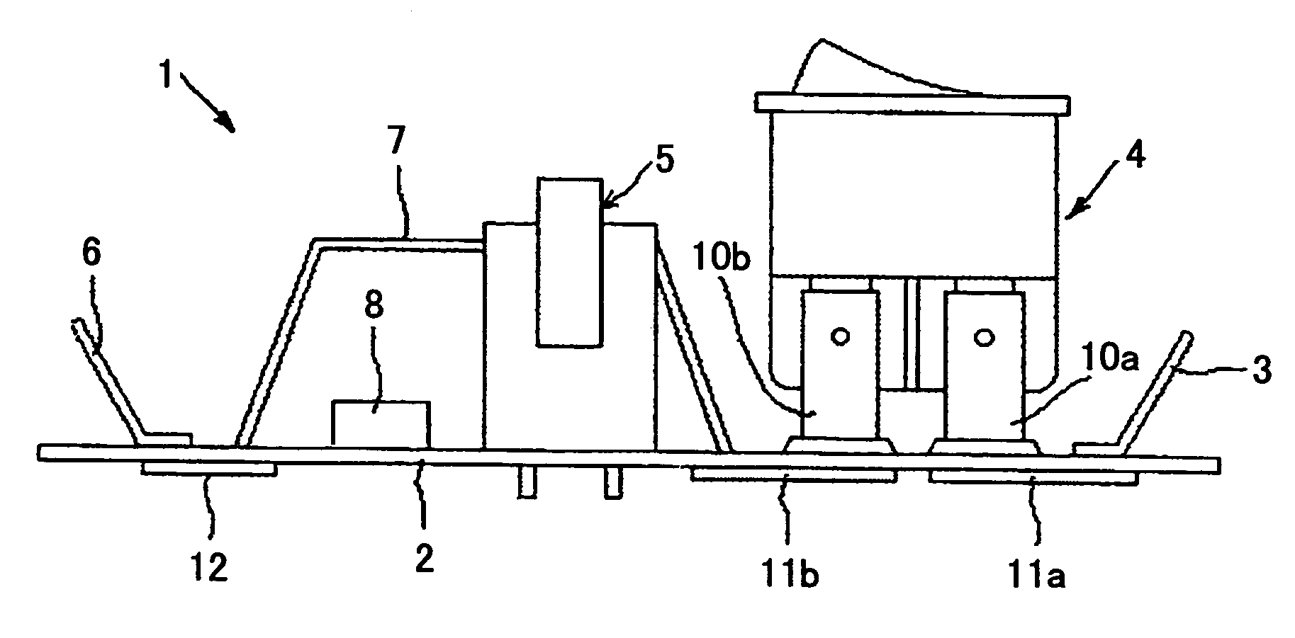
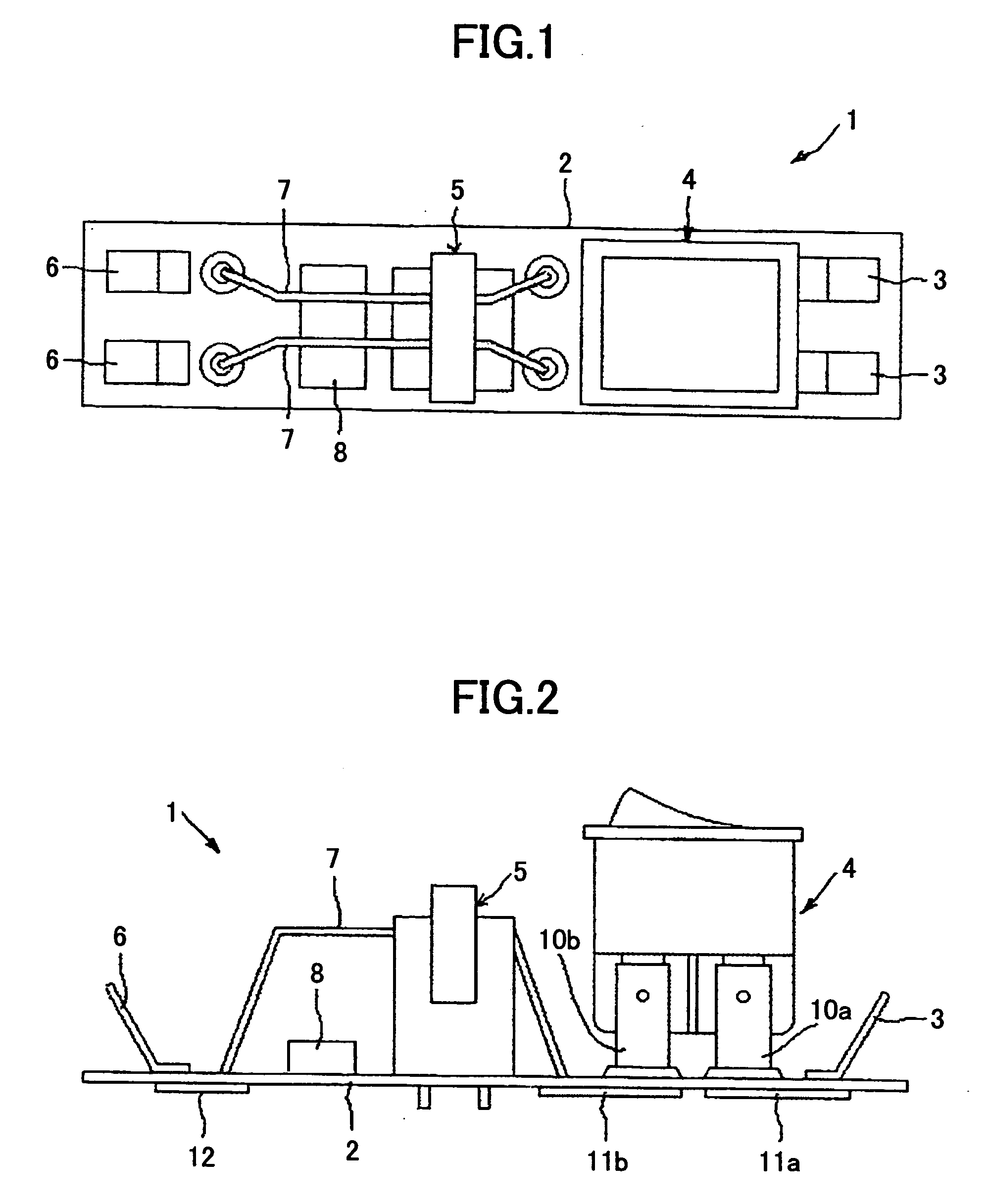
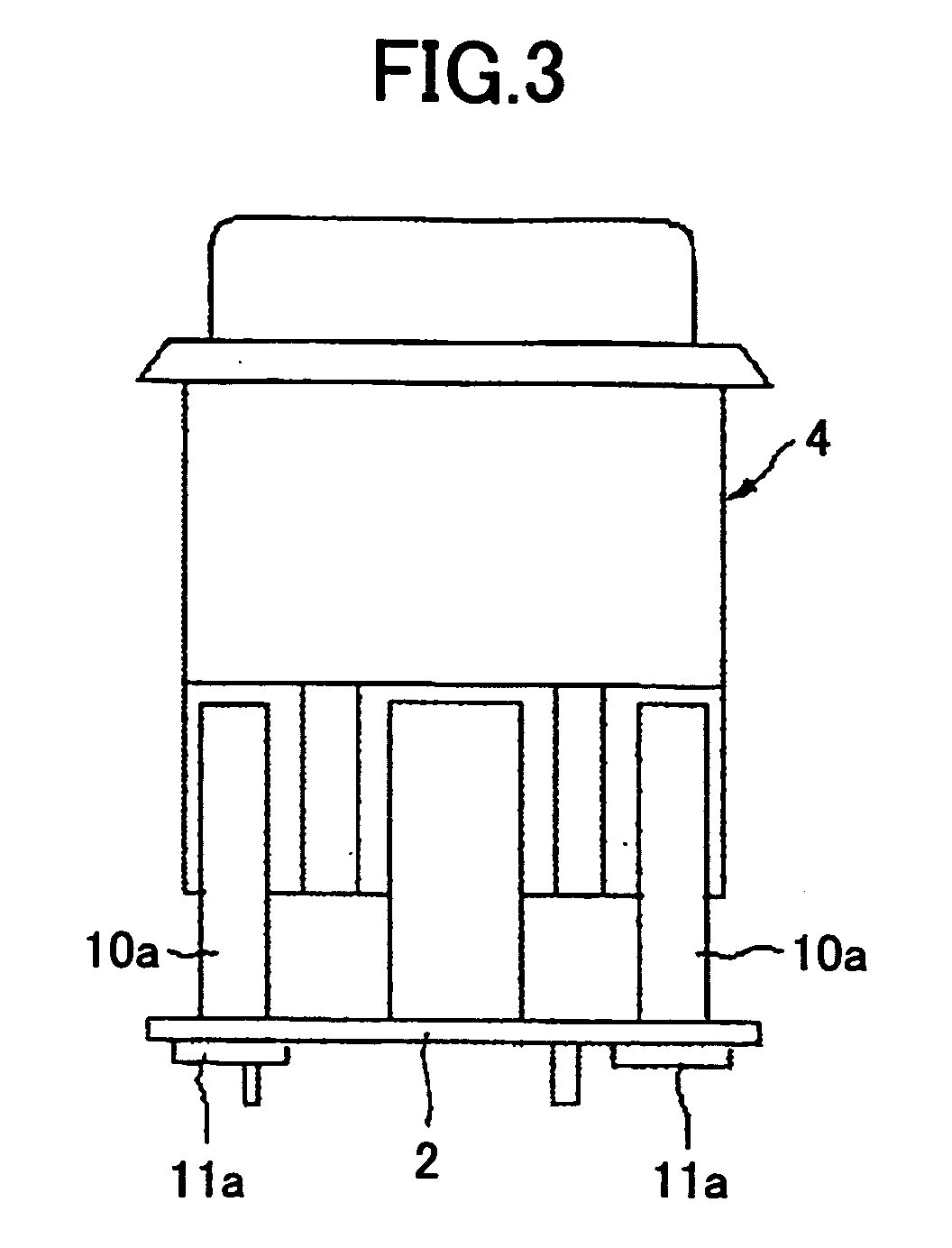
[0057] A first embodiment of a switching device and electric equipment in accordance with the present invention is described. FIGS. 1 through 8 illustrate the first embodiment of a switching device in accordance with the present invention. FIG. 1 is a plan view of the switching device. FIG. 2 is a front view of the switching device. FIG. 3 is an enlarged right side view of the switching mechanism of the switching device. FIG. 4 is a circuit diagram of the switching device. FIGS. 5 through 8 are enlarged front views illustrating the operation of the switching device, showing various states of the switching mechanism. FIG. 9 is a perspective rear view of a printer that is an example of electric equipment to which the switching device is applied.

[0058] As shown in FIGS. 1 and 2, the switching device 1 of the first embodiment includes a pair of input connecting terminals 3, a switching mechanism unit 4, a leakage detecting current transformer 5, a pair of output connecting terminals 6,...

second embodiment

[0109] Referring now to FIGS. 10 through 16, a second embodiment of a switching device and an electric apparatus in accordance with the present invention is described. FIG. 10 is a circuit diagram of the switching device of the second embedment. The switching device 30 of this embodiment is the same as the switching device 1 of the first embodiment, except for the component equivalent to the switch drive control circuit 8 shown in FIG. 4. Accordingly, the structure including the switching mechanism unit 4 and the leakage detecting current transformer 5 illustrated in FIGS. 1 through 3 and FIGS. 5 through 8 is the same as that of the first embodiment. In FIG. 10, the same components as those shown in FIG. 4 are denoted by the same reference numerals as those in FIG. 4.

[0110] As shown in FIG. 10, the switching device 30 of the second embodiment includes the switching mechanism unit 4, the leakage detecting current transformer 5, the amplifier circuit 21, and the switch control circui...


PUM


Abstract

A switching device is provided that includes a switching mechanism unit and a switch drive control circuit. In the switching device, an operating member is maintained in an ON position by the sucking force of a permanent magnet and a yoke, despite the pushing force of a biasing unit, when the permanent magnet is in an ON position. The yoke is magnetized in such a manner as to reduce the magnetic force of the permanent magnet, when a coil wound around the yoke is energized by the switch drive control unit. The operating member and a switching member are moved from the ON position to the OFF position by virtue of the pushing force of the biasing unit, thereby shutting a feed line.

Description

BACKGROUND OF THE INVENTION [0001] 1. Field of the Invention [0002] The present invention relates to a switching device, and, more particularly, to a switching device that is easy to operate and is so small as to be disposed in the housing of an electric apparatus such as a copying machine, a printer, or a personal computer, and can be used for at least either leakage prevention or excess voltage prevention. The present invention also relates to such an electric apparatus. [0003] 2. Description of the Related Art [0004] There have been ground-fault interrupters as domestic wiring devices for detecting and shutting off leakage in domestic wirings (see Japanese Laid-Open Patent Application Nos. 2000-261953, 2001-023501, and 2001-006515). The structures and forms of the conventional ground-fault interrupters are standardized in accordance with the JIS (Japanese Industrial Standards), and the necessary components are housed in standardized housings. [0005] For example, the ground-fault ...

Claims


Application Information

Patent Timeline
Patent Type & Authority Applications(United States)
IPC IPC(8): H01H47/00H01H71/32H01H73/40H01H77/08H01H83/02H01H83/10
CPCH01H71/32H01H83/10H01H83/02H01H73/40
Inventor NOGUCHI, YUKIOGOTOH, AKIHIRO
Owner RICOH KK
Why Eureka
Try Eureka