Signal processor for converting signal

a signal processor and signal technology, applied in the direction of electromagnetic transmission, electrical apparatus, transmission, etc., can solve the problems of large system damage, small nonlinear phenomena, and nonlinear disturbances, and achieve the effect of high extinction ratio

Inactive Publication Date: 2005-12-15
ELECTRONICS & TELECOMM RES INST
View PDF4 Cites 2 Cited by
  • Summary
  • Abstract
  • Description
  • Claims
  • Application Information

AI Technical Summary

Benefits of technology

[0013] The present invention is directed to a signal processor for converting a sig...

Problems solved by technology

However, when the NRZ signal is used in a wavelength division multiplexing, signals having different wavelengths are more often overlapped in time than RZ signal, which leads to a nonlinear disturbance.
In addition, compared with the NRZ signal, the RZ signal is less overlapped in time, thus resulting in small nonlinear phenomena.
However, in this case, there are various problems in that the signal intensity varies across an optical fiber, and that the system is affected a lot by dispersion characteristics, a transmission distance and nonlinear characteristics of the optical fiber.
However, for example, when a series of RZ signals of 10 GHz having a short pulse width is incident on the wavelength converter, as long as a special apparatus is not provided, this method will generate a phase recovery speed of the semiconductor optical amplif...

Method used


Image

  • Signal processor for converting signal
  • Signal processor for converting signal
  • Signal processor for converting signal

Examples


Embodiment Construction

[0024] The present invention will now be described more fully hereinafter with reference to the accompanying drawings, in which preferred embodiments of the invention are shown. This invention may, however, be embodied in different forms and should not be construed as limited to the embodiments set forth herein. Rather, these embodiments are provided so that this disclosure will be thorough and complete, and will fully convey the scope of the invention to those skilled in the art.

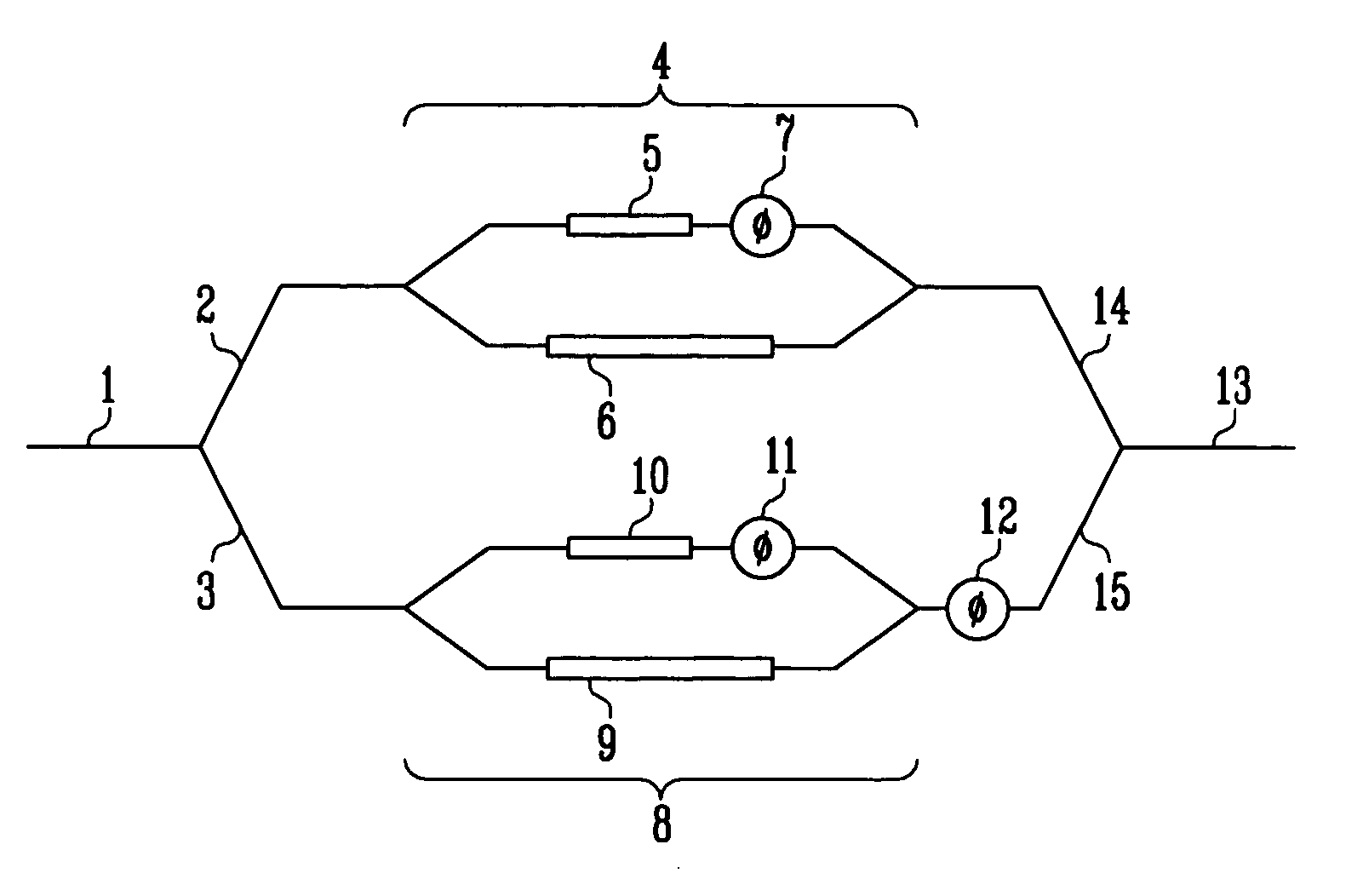
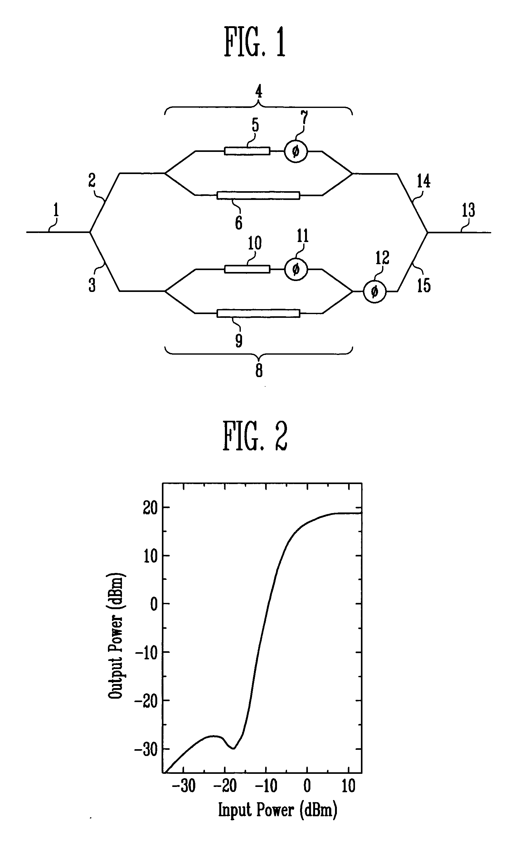
[0025]FIG. 1 is a schematic diagram of a signal processor for converting a signal according to the present invention.

[0026] Waveguides 2 and 3 having different lengths are connected to an output stage of an input waveguide 1, respectively, and 2R regenerators 4 and 8 are connected to the waveguides 2 and 3, respectively. An output stage of the 2R regenerator 4 is connected to an output waveguide 13 through a waveguide 14, and an output stage of the 2R regenerator 8 is connected to the output waveguide 13 ...


PUM


Abstract

Provided is a signal processor for converting a signal that converts a return to zero (RZ) signal into a non-return to zero (NRZ) signal, in which two 2R (re-amplifying, re-shaping) regenerators are connected in parallel between an input waveguide and an output waveguide with different lengths from each other. The 2R regenerator includes: two semiconductor optical amplifiers having different lengths from each other; and phase control means connected to a short semiconductor optical amplifier. The RZ signal input by a length difference of the waveguide is delayed by a time difference of a half of one bit so that the 2R regenerated NRZ signal can be obtained.

Description

CROSS-REFERENCE TO RELATED APPLICATION [0001] This application claims priority to and the benefit of Korean Patent Application No. 2004-101658, filed Dec. 6, 2004, the disclosure of which is incorporated herein by reference in its entirety. BACKGROUND [0002] 1. Field of the Invention [0003] The present invention relates to a signal processor for converting a signal, and more specifically, to a signal processor for converting a signal that performs 2R (re-amplifying, re-shaping) regeneration while converting a return to zero (RZ) signal into a non-return to zero (NRZ) signal. [0004] 2. Discussion of Related Art [0005] In general, an optical signal for use in an optical communication system is classified into an RZ signal and an NRZ signal. [0006] The NRZ signal is obtained by modulating a continuous wave (CW). Therefore, it is rather simply generated relative to the RZ signal and less sensitive to a timing jitter than the RZ signal. The bandwidth of an optical receiver for the NRZ si...

Claims


Application Information

Patent Timeline
IPC IPC(8): H04B10/02H04B10/155
CPCH04B2210/517H04B10/516H04B10/00
Inventor KIM, DONG CHURLYEE, DAE SULEEM, YOUNG AHNSIM, EUN DEOKPARK, KYUNG HYUN
Owner ELECTRONICS & TELECOMM RES INST
Why Eureka
Try Eureka