Occludator, face bow, occlusion-confirming system and temporomandibular joint-reproducing system

a technology of occludator and occlusion, which is applied in the field of occludator, face bow, occlusionconfirming system and temporomandibular jointreproducing system, can solve the problems of less adjustment, inevitably occurring errors in mandibular movements reproduced by semi-adjustable occludators, and the possibility of prosthesis failure due to any of these errors

Inactive Publication Date: 2005-12-15
NIHON UNIVERSITY
View PDF10 Cites 24 Cited by
  • Summary
  • Abstract
  • Description
  • Claims
  • Application Information

AI Technical Summary

Benefits of technology

[0109] Moreover, the conventional occludator cannot express a change of an articular fossa and a mandibular condyle between ages. Products have been fabricated only by a linear articular fossa and a contact shaped like a ball. Howev

Problems solved by technology

However, some errors inevitably occur in mandibular movements reproduced by a semi-adjustable occludator which is less capable of adjustment.
A prosthesis fabricated by such an occludator may cause an error which is collision with or separation from opposed teeth during lateral movements.
Particularly when providing balanced occlusion for a full denture, a prosthesis may fail due to any of these errors.
However, when a number of teeth are lost or in the case of a full denture, a stretch of the theory suggests that flat surfaces are better for the occlusion planes of artificial teeth, which may lead to misinterpretation.
Flat occlusion planes

Method used


Image

  • Occludator, face bow, occlusion-confirming system and temporomandibular joint-reproducing system
  • Occludator, face bow, occlusion-confirming system and temporomandibular joint-reproducing system
  • Occludator, face bow, occlusion-confirming system and temporomandibular joint-reproducing system

Examples


embodiment 1

[0155] Embodiment 1 of the present invention will be described below in accordance with the accompanying drawings.

[0156] First, the following will discuss the configuration of an occludator K used for the present system.

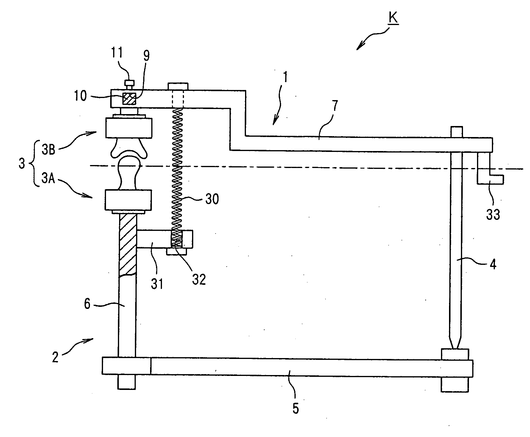
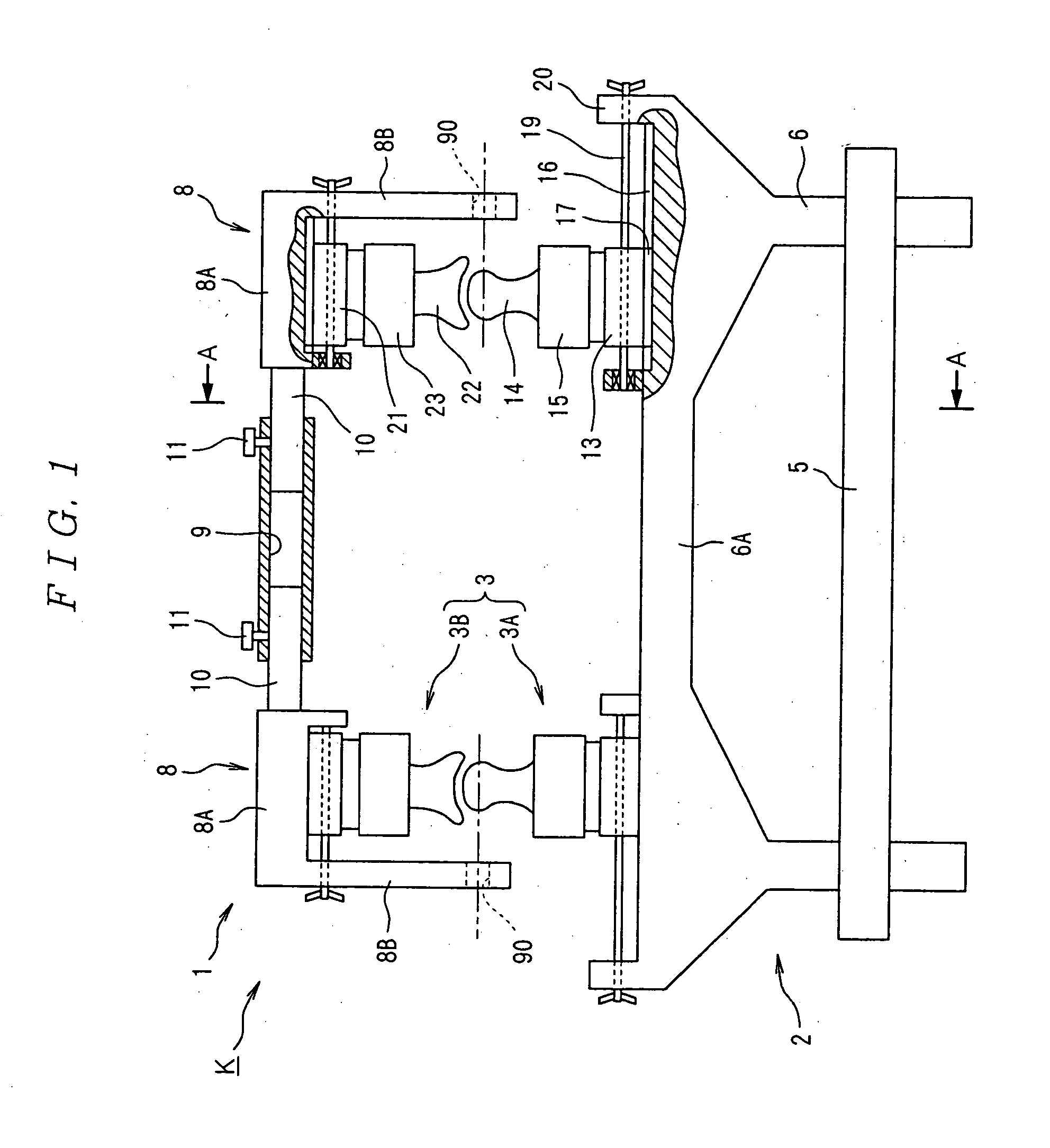
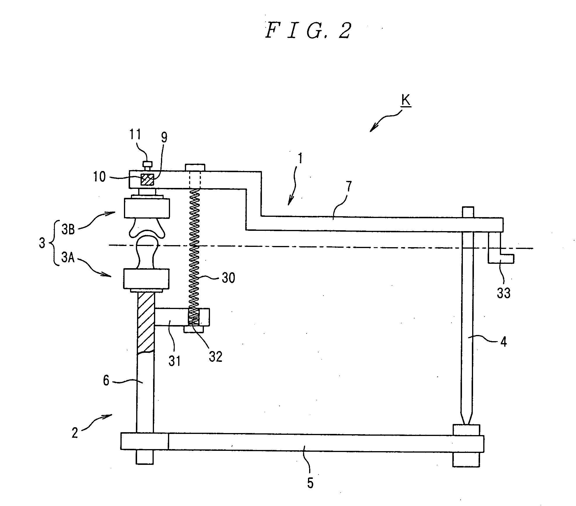
[0157] As shown in FIGS. 1 and 2, the occludator K of the present embodiment is constituted of an upper bow-shaped part 1, a lower bow-shaped part 2, a joint 3 for connecting the upper bow-shaped part 1 and the lower bow-shaped part 2, and an incisal pin 4. To enhance understanding, a mandibular condyle model 14 and a maxillary fossa model 22, which are vertically opposed to each other, are not in contact with each other in some drawings below. In reality, the models are in contact with each other (contact state) or an elastic sheet material (not shown, the material is made of a material such as silicon and is preferably equal in elastic modulus to an articular disk) equal in thickness to a gap between joints is interposed between the models. Further, to enhance und...

embodiment 2

[0262] Embodiment 2 will be described below in accordance with the accompanying drawings. The same components as the above-described embodiment will be indicated by the same reference numerals and characters.

[0263] The basic configuration of Embodiment 2 is similar to that of Embodiment 1. A face bow F and a part of an occludator that corresponds to the face bow F are different from those of Embodiment 1.

[0264] First, the configuration of the face bow F of the present embodiment will be discussed below.

[0265] As shown in FIGS. 25 to 27, in the body of the face bow F, legs 100 on the right and left are symmetrically opposed to each other. Each of the legs 100 is shaped like a letter L in plan view. The leg 100 is constituted of a leg body 101 which stretches to the front and rear and a platy horizontal part 102 which is connected to the base of the leg body 101 and stretches to the other opposed leg 100.

[0266] As shown in FIG. 26, the right and left horizontal parts 102 are vertic...

embodiment 3

[0291] Embodiment 3 will be described below in accordance with the accompanying drawings. The same members as the above-described embodiments will be indicated by the same reference numerals and characters.

[0292] The basic configuration of Embodiment 3 is similar to that of Embodiment 2. A face bow F is different from that of Embodiment 2.

[0293] Referring to FIGS. 33 to 35, the face bow F of the present embodiment will be discussed below.

[0294] As with Embodiment 2, right and left legs 100 of the present embodiment are shaped like letters L in plan view, and right and left horizontal parts 102 are vertically overlaid on the other. However, in the present embodiment, a long opening stretching in a lateral direction is formed in each of the horizontal parts 102. The horizontal parts 102 are guided by a box 122 so as to move only in the lateral direction. The top plate and the bottom plate of the box 122 have tapped holes in positions vertically opposed to the long openings formed in...


PUM


Abstract

It is intended to provide an occludator whereby joint movements at occlusion being similar to the actual tempromandibular joint movements of an individual patient or ideal movements can be reproduced, and a face bow to be used for the occludator. To achieve this object, an occlusion plane against a standard plane is accurately drawn by using the above face bow F whereby the occlusion plane can be drawn at a high accuracy. A solid model of the tempromandibular joint similar to the tempromandibular joint form of an actual patient is used as the joint unit of the occludator K, while the positional relationship in the body at occlusion is three-dimensionally reproduced in the occludator I with the use of the above-described face bow F. It is also intended to provide an occlusion-confirming system and a tempromandibular joint-reproducing system with the use of an occludator whereby joint movements at occlusion being similar to the actual tempromandibular joint movements of an individual patient or ideal movements can be reproduced. To achieve this object, the tempromandibular joint of the body is photographed with a local X-ray CT device to give three-dimensional image data and then a solid model of the tempromandibular joint is constructed based on the three-dimensional image data. This solid model is employed as the joint unit of the occludator K and the positional relationship in the body at occlusion is three-dimensionally reproduced.

Description

TECHNICAL FIELD [0001] The present invention relates to a dental occludator for confirming occlusion, a face bow for the occludator, an occlusion confirming system which can be used for the fabrication of a prosthesis for teeth and treatment of a temporomandibular joint, etc., and a temporomandibular joint reproducing system usable for the occlusion confirming system. BACKGROUND ART [0002] As described in JP2000-262545A (see FIG. 1), a conventional occludator comprises, e.g., a lower bow-shaped part where a lower jaw tooth mold is mounted, an upper bow-shaped part where an upper jaw tooth mold is mounted, and a joint for connecting the lower bow-shaped part and the upper bow-shaped part, so that an artificial joint movement such as opening / closing of the tooth molds is obtained and a state of occlusion is reproduced. The occludator is used in the treatment of the occlusion of upper and lower teeth and the fabrication of prostheses. [0003] The joint described in the conventional docu...

Claims


Application Information

Patent Timeline
IPC IPC(8): A61C11/00A61C11/02A61C19/045
CPCA61C11/005A61C19/045A61C11/022B33Y80/00
Inventor ARAI, YOSHINORIAKIYAMA, YUTAKAISHIZUKA, TORUTSUNASHIMA, HITOSHIYAMADA, AYUTA
Owner NIHON UNIVERSITY
Why Eureka
Try Eureka