High-density reaction chambers and methods of use

Inactive Publication Date: 2005-12-15
MASSACHUSETTS INST OF TECH
View PDF0 Cites 166 Cited by
  • Summary
  • Abstract
  • Description
  • Claims
  • Application Information

AI Technical Summary

Benefits of technology

[0022] In yet another aspect of the invention, a combination microtiter plate and microfluidics device is provided that is useful to perform genetic tests on a series of patient samples simultaneously, which may reduce the cost and increase the speed of genetic testing. In another embodiment, the invention provides a device that enables samples to be reused for new genetic tests. In another embodiment, the invention provides a

Problems solved by technology
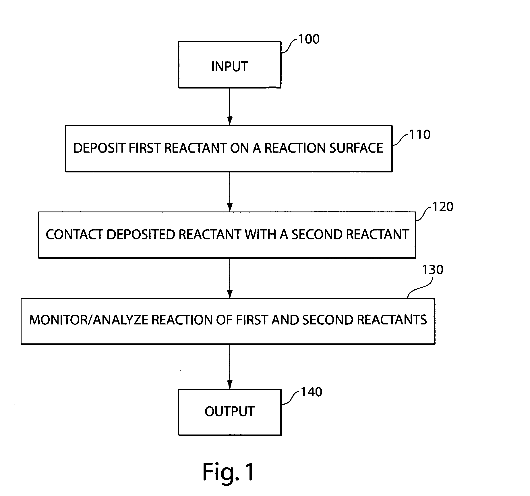
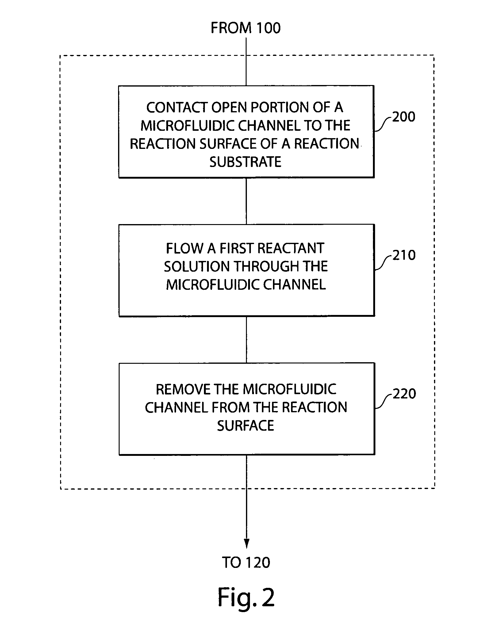
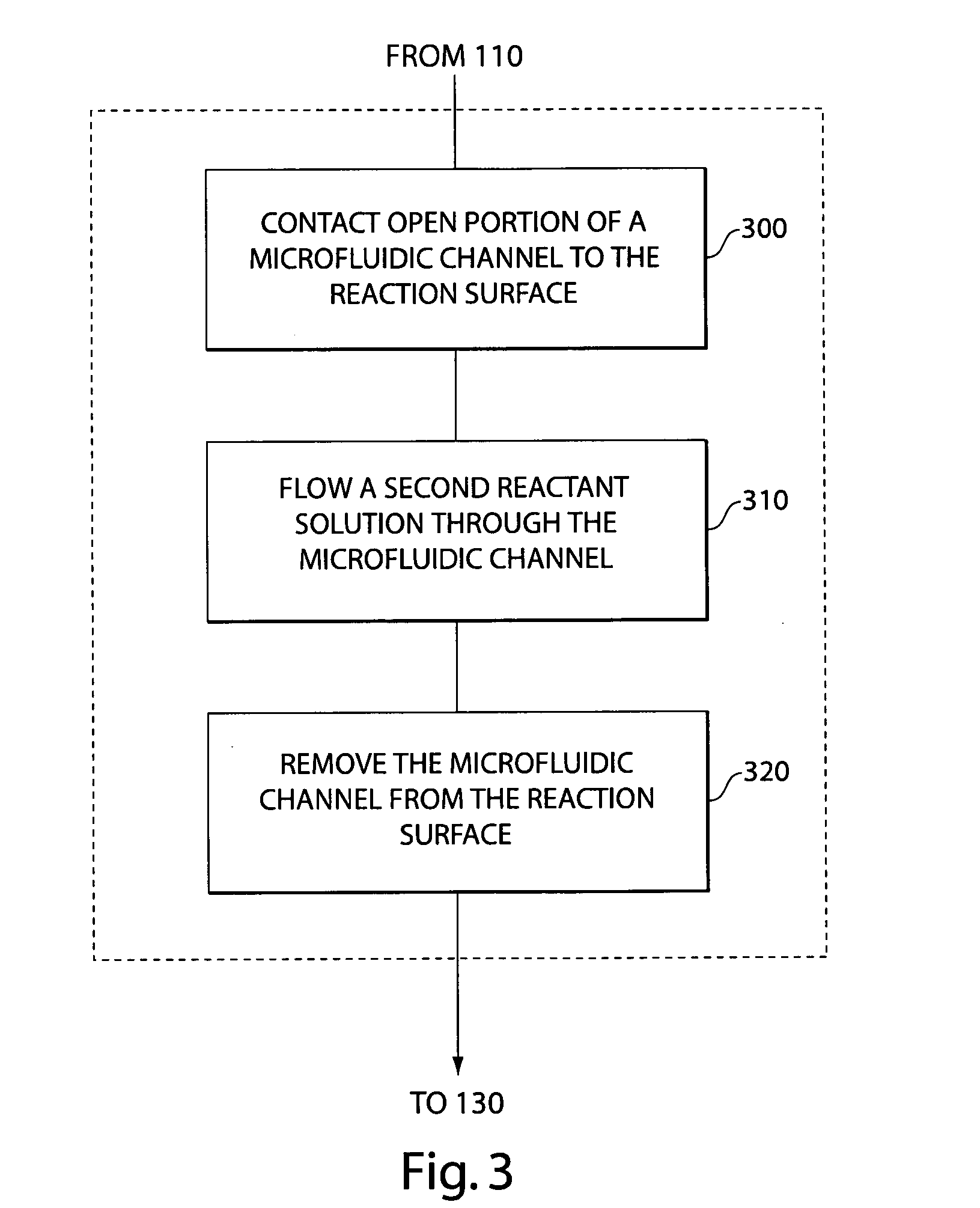
Research efforts that use population studies to identify associations between different diseases and genetic characteristics are limited by the cost of molecular testing.
The use of routine genetic testing in clinical settings also has been limited by the high cost of individual assays.
In this regard, this technology may not be used effectively for simultaneously testing many samples, such as from multiple patients,

Method used


Image

  • High-density reaction chambers and methods of use
  • High-density reaction chambers and methods of use
  • High-density reaction chambers and methods of use

Examples


example 1

Parallel Lines of DNA on a Glass Slide

[0293]FIG. 18 shows an embodiment where an array of microchannels was used to immobilize DNA into parallel lines on a glass slide. The round spots at the top of the image are wells or inlets where individual DNA samples were introduced to the array of microchannels. These wells are fluidically attached to channels that direct the DNA along the glass slide, where it is immobilized. The array of microchannels was then removed, and the slide was exposed to cyber green dye to make the lines of DNA visible. While these lines are approximately 50 microns in width, in other embodiments, they may be as small as 10 microns in width or smaller.

example 2

Matrix of Hybridization Reactions

[0294]FIG. 20 shows a micrograph of a 96-channel microfluidic device that was used in the experiments described below. Fluid inlet ports 73 are shown (these ports are through holes that are in communication with the upper surface). Each microchannel 54 is 50 microns wide (these are on the lower surface). The device was first placed on a glass slide with the channels oriented vertically. Sample DNA was then allowed to flow through a selected number of channels for less than a minute before it was removed from the channels. The device then was removed from the slide. The slide then was treated to bond the sample DNA to the glass slide, followed by blocking to prevent any other DNA from adhering to it. The same microfluidic device was again applied to the glass slide with the channels oriented horizontally. Selected channels were then filled with labeled probe DNA, and the assembly was allowed to incubate for 12 hours. Subsequently, the microfluidic de...

example 3

Reuse of Patient Samples for New Targets

[0297] The arrays of the invention allow for sequential assays to be performed on sample DNA that has been attached to a reaction surface. Reuse of sample DNA provides two significant advantages: a) the cost of sample preparation can be spread over many uses, and b) the sample can be probed for new targets that were not contemplated when the DNA sample was originally prepared. According to the invention, samples deposited on a reaction surface can be conserved for tests to be performed at a future date.

[0298] In preferred embodiments of the invention, whole genome amplifications are performed and the resulting DNA samples are deposited on the reaction surface. As a result, all targets contained in the genome are potentially available. Therefore, once the DNA on the reaction surface has been exposed to channels of a first set of hybridization probes, other targets are still available for future hybridization assays.

[0299] Once a hybridizatio...


PUM

PropertyMeasurementUnit
Lengthaaaaaaaaaa
Lengthaaaaaaaaaa
Thicknessaaaaaaaaaa

Abstract

Methods and devices for performing multiple simultaneous reactions on a reaction surface are disclosed. Methods and devices for simultaneously interrogating multiple patient samples with multiple diagnostic reagents are disclosed.

Description

RELATED APPLICATION [0001] This application claims benefit under 35 U.S.C. 119(e) of U.S. provisional patent application 60 / 514,887, filed Oct. 27, 2003, the entire content of which is incorporated herein by reference.BACKGROUND OF INVENTION [0002] 1. Field of Invention [0003] The invention generally relates to methods and devices for performing high throughput biological assays. In particular, the invention relates to microarray methods and devices for nucleic acid diagnostic assays. [0004] 2. Discussion of Related Art [0005] There is an ongoing need to reduce the cost of molecular assays for both research and clinical applications. Research efforts that use population studies to identify associations between different diseases and genetic characteristics are limited by the cost of molecular testing. The use of routine genetic testing in clinical settings also has been limited by the high cost of individual assays. Nonetheless, an increasing number of genetic targets have been show...

Claims


Application Information

Patent Timeline
IPC IPC(8): B01L3/00B01L3/02B01L9/00B01L99/00C12M1/34C12Q1/68G01N35/00G01N35/10
CPCB01J19/0046G01N2035/1034B01J2219/00317B01J2219/00369B01J2219/00527B01J2219/00563B01J2219/00574B01J2219/00576B01J2219/00585B01J2219/00596B01J2219/00657B01J2219/00659B01J2219/00722B01J2219/00725B01L3/021B01L3/0293B01L3/5025B01L3/502715B01L3/563B01L9/543B01L2200/021B01L2200/025B01L2200/027B01L2300/0819B01L2300/0829B01L2400/0406B01L2400/0409B01L2400/0415B01L2400/0487G01N35/1011G01N2035/00158B01J2219/00315
Inventor BENN, JAMES A.COOPER, MATSTHORSEN, TODD
Owner MASSACHUSETTS INST OF TECH
Why Eureka
Try Eureka