

Semiconductor memory
Image

Examples
first embodiment
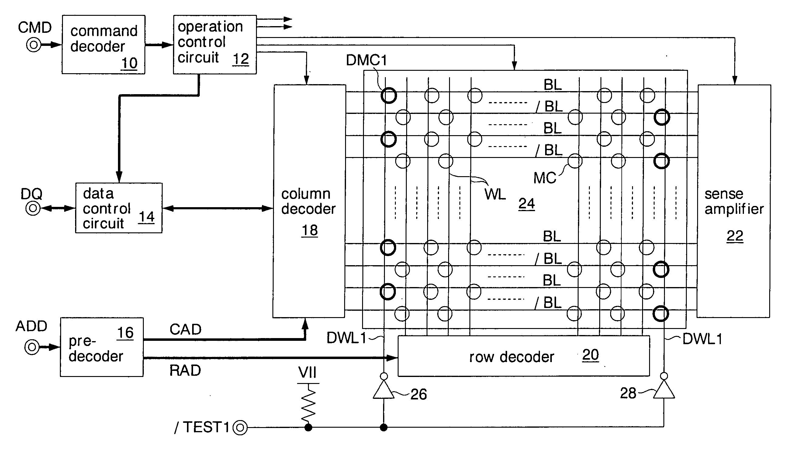
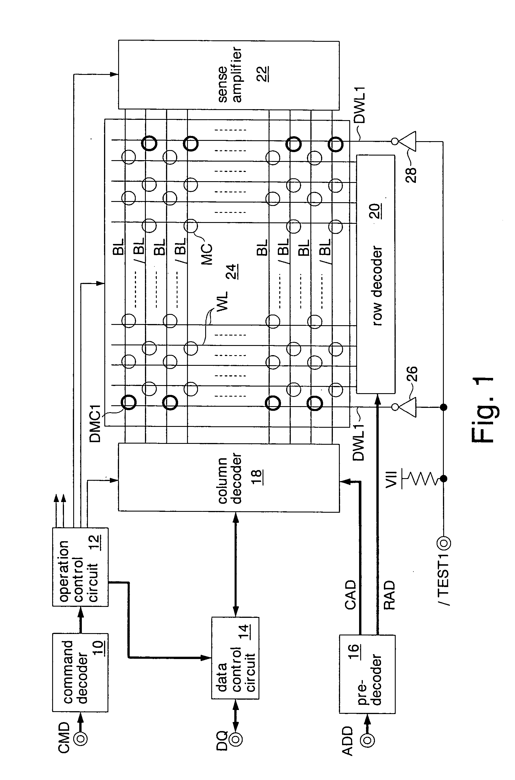
[0032]FIG. 1 shows a semiconductor memory according to the present invention. This semiconductor memory is formed as a DRAM on a silicon substrate by using a CMOS process. The DRAM includes a command decoder 10, an operation control circuit 12, a data control circuit 14, a pre-decoder 16, a column decoder 18, a row decoder 20, a sense amplifier 22, and a memory cell array 24.
[0033] The command decoder 10 receives a command signal CMD (e.g., a row address strobe signal / RAS, a column address strobe signal / CAS, and a chip select signal / CS) supplied via a command terminal, decodes a command (e.g., an access command (a read command and a write command) and a refresh command) indicated by the received command signal CMD, and outputs an internal command signal corresponding to the decoding result to the operation control circuit 12.
[0034] The operation control circuit 12 generates a plurality of operation control signals for operating the memory cell array 24 in accordance with the int...
third embodiment
[0074] The memory cell array 24C further includes a dummy bit line DBL2 (the second dummy signal line) on the outside of each dummy bit line DBL1 (the first dummy signal line) of the The outer dummy bit line DBL2 is connected to the precharge voltage line VPR. To the dummy bit line DBL2, dummy memory cells DMC2 (the second dummy memory cells) are connected. The dummy memory cells DMC1 and DMC2 have the same shape (layout) and electric characteristics as those of the real memory cell MC.
second embodiment
[0075] In this embodiment, as in the second embodiment, in order to write data of level H onto the dummy memory cell DMC1 that is required for applying stress to a real memory cell MC, the internal supply voltage VII (level H) is supplied to the dummy bit line DBL1. On the other hand, the dummy bit line DBL2, that is connected to the dummy memory cells DMC2 onto which data of level H is not to be written, is connected to the precharge voltage line VPR. Since the dummy bit line DBL2 is not driven, the drivability of the inverters 30 and 32 can be made small, thus reducing the chip size of the DRAM.
[0076] In this embodiment, the same effects as those described in the first, second, and third embodiments can be also achieved.
[0077] In the aforementioned embodiments, an example has been described in which the present invention is applied to a DRAM. However, the present invention is not limited thereto. For example, the present invention may be applied to other semiconductor memories, s...
PUM
 Abstract
Description
Claims
Application Information
- IPC
- G11C5/00; G11C7/02; G11C7/14; G01R31/28; G11C11/401; G11C11/4099; G11C29/00; G11C29/06; G11C29/24
- CPC
- G11C7/14; G11C11/401; G11C2029/5006; G11C29/24; G11C29/50; G11C11/4099
- Inventors
- YAMADA, SHINICHI; FUJIEDA, WAICHIRO