

Delay-locked loop and a method of testing a delay-locked loop
a delay-locked loop and loop technology, applied in the field of integrated circuits (ics), can solve the problems of unvarying relationship, inability to test a dll to determine whether it works, and variability of the overall delay produced by the buffer tr
- Summary
- Abstract
- Description
- Claims
- Application Information
AI Technical Summary
Benefits of technology
Problems solved by technology
Method used
Image

Examples
Embodiment Construction
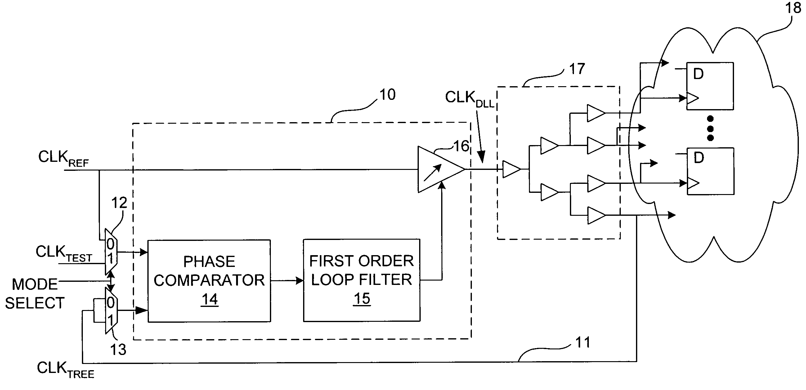
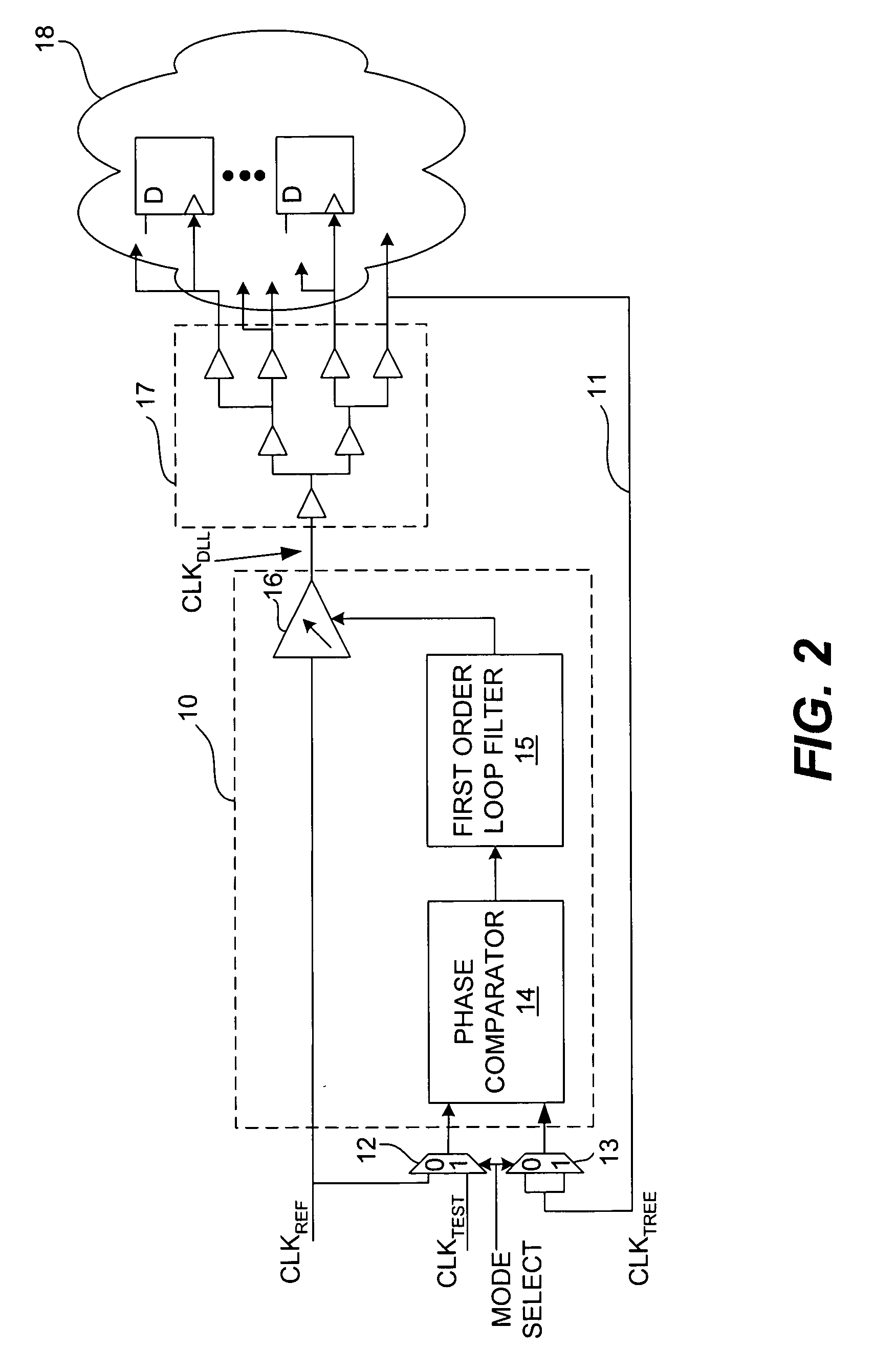
[0021] In accordance with the present invention, a DLL is provided that includes test circuitry that allows a test clock to be input to the DLL to cause the variable delay element inside the DLL to be exercised. FIG. 2 is a block diagram of the DLL 10 of the present invention in accordance with an exemplary embodiment. The DLL 10 has two multiplexers (MUX) 12 and 13 that control the selection of signals input to the phase comparator 14 of the DLL 10. The MUX 12 selects either the test clock, CLKTEST, or the reference clock, CLKREF. When the mode select signal is not asserted, the MUX 12 selects CLKREF to be input to the phase comparator 14. When the mode select signal is asserted, the MUX 12 selects CLKTEST to be input to the phase comparator 14.
[0022] MUX 13, which is optional, receives the clock of clock buffer tree 17, CLKTREE, on feedback path 11 at both of its inputs. Therefore, regardless of the state of the mode select signal, CLKTREE will always be selected to be input to t...
PUM
 Abstract
Description
Claims
Application Information