Injection locking type or MOPA type of laser device
a laser device and locking type technology, applied in laser devices, laser details, active medium materials, etc., can solve the problems of difficult to find a laser device suitable for oscillators, titanium sapphire laser devices producing very low output energy, etc., to facilitate compensation and accurately compensate jitter
- Summary
- Abstract
- Description
- Claims
- Application Information
AI Technical Summary
Benefits of technology
Problems solved by technology
Method used
Image
Examples
first embodiment
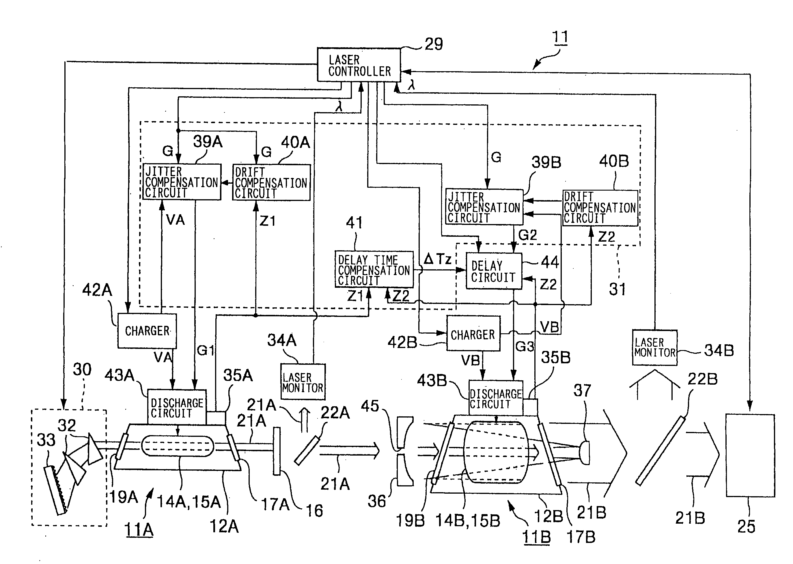
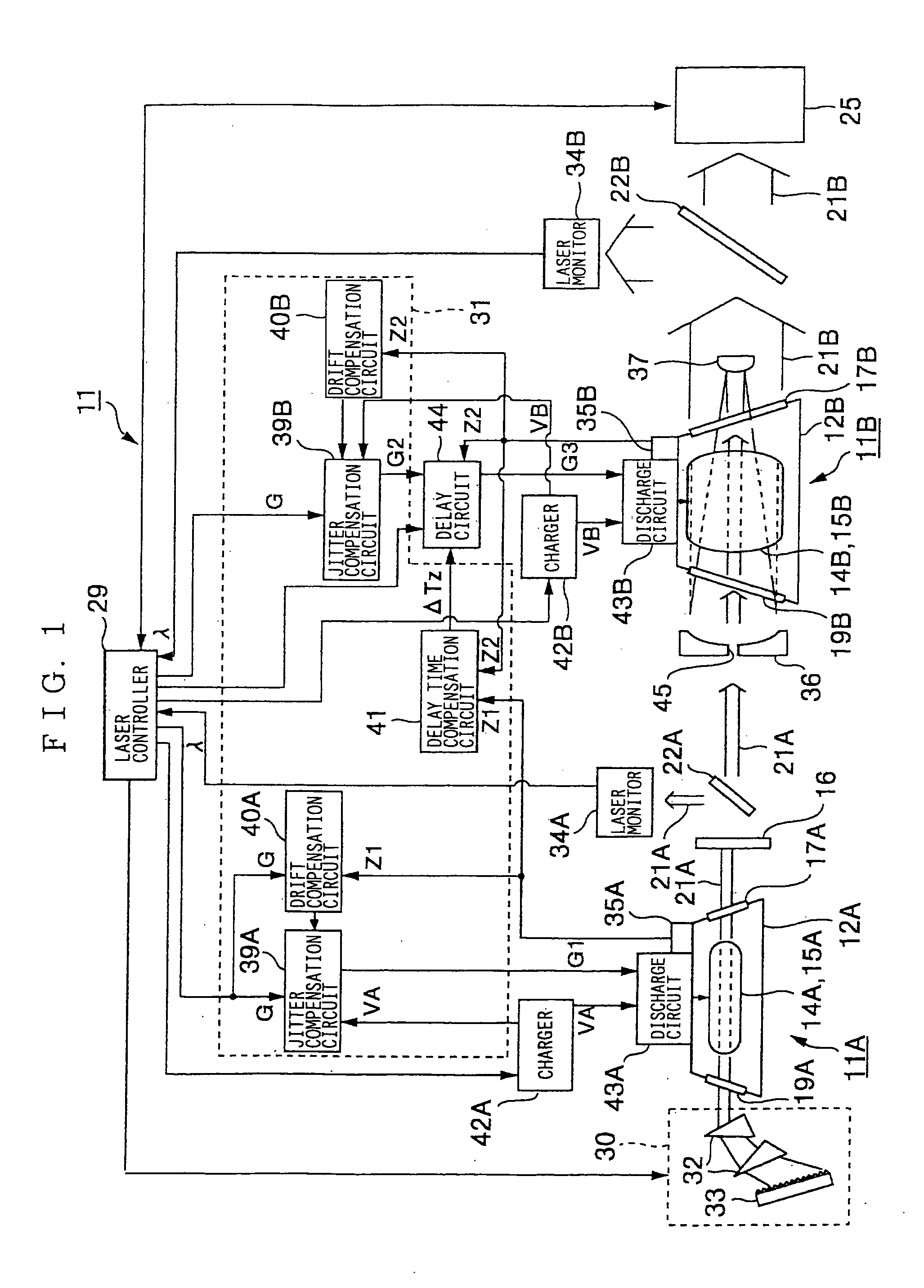
[0115] As explained above, in the injection locking type of fluorine laser device 11, the oscillator 11A and the amplifier 11B are provided with the jitter compensation circuits 39A and 39B for compensating jitter, respectively. As a result, each of the oscillator 11A and the amplifier 11B carries out discharge in a constant for the trigger signal G, and a timing in which the amplified laser light 21B is emitted becomes constant. Accordingly, the amplified laser light 21B is always incident on the aligner 25 in a constant timing, and therefore work is favorably carried out.
[0116] Further, since the light emission of the seed laser light 21A and the light emission of the amplified laser light 21B, or the start of oscillator discharge and the start of amplification discharge are always synchronized, the amplified laser light 21B with desired laser parameters can be obtained, and work can be favorably performed. Further, jitter compensation is carried out based on the oscillator volta...
second embodiment
[0119] However, if the amplified laser light require time from the output of the trigger signal G until the amplified laser light 21B is incident on the aligner 25 is not substantially constant, it is unclear when the amplified laser light 21B is incident thereon, and work cannot be favorably carried out. For this reason, in the second embodiment, compensation is carried out so that the seed laser light elapsed time, which is taken from the output of the trigger signal G to the light emission of the seed laser light 21A, becomes constant.
[0120] As described above, the delay circuit 44 performs a control so that the delay time ΔT from the light emission of the seed laser light 21A to the light emission of the amplified laser light 21B, or from the start of oscillator discharge to the start of amplification discharge becomes the optimal delay time ΔT0. Accordingly, by making the seed laser light elapsed time, which is from the trigger signal G to the light emission of the seed laser l...
PUM
 Abstract
Description
Claims
Application Information
 - R&D
- Intellectual Property
- Life Sciences
- Materials
- Tech Scout
- Unparalleled Data Quality
- Higher Quality Content
- 60% Fewer Hallucinations
Browse by: Latest US Patents, China's latest patents, Technical Efficacy Thesaurus, Application Domain, Technology Topic, Popular Technical Reports.
© 2025 PatSnap. All rights reserved.Legal|Privacy policy|Modern Slavery Act Transparency Statement|Sitemap|About US| Contact US: help@patsnap.com


