Method for medical 3D image display and processing, computed tomograph, workstation and computer program product

Inactive Publication Date: 2005-12-22
SIEMENS AG
View PDF10 Cites 9 Cited by
  • Summary
  • Abstract
  • Description
  • Claims
  • Application Information

AI Technical Summary

Benefits of technology

[0031] The method provides for the second pixel in the extended search region to be determined on the basis of an extended value range for a pixel value, i.e. on the basis of an extended pixel value range. The second pixel is thus possibly determined on the basis of a new pixel value, which does not need to match the original pixel value. In this way, it is possible to refine or improve the targeted diagnosis of relevant details in the extended search range.
[0034] If appropriate, the examiner may also be provided with a number of preferable, possibly automatically determined, search regions within the context of a menu selection. This prevents an extended search region from being chosen to be too small, which would mean that too little depth information were then available. Secondly, it prevents an extended search region from turning out to be too large, so that proximity to a region with high contrast, e.g. a part of the skeleton or bone region, is avoided. This is because vessels filled by the skeleton or with contrast agent are normally structures which are distinguished from their surroundings by particularly high levels of contrast and would therefore be able to mask the details which are actually to be examined. Depending on the diagnostic situation, it may thus be advantageous to prescribe an extended search region which is specifically tuned and quantified for the diagnostic situation.
[0035] Preferably, the search beam is parameterized in the extended search region. Parameterization of the search beam is advantageous for computer processing and quantification of the extended search region.
[0039] One particular advantage is interactive or automatic selection of the second pixel as alternative or additional pixel. Thus, by way of example, it is possible to implement an automatic search for a lesion in the method. A lesion is generally to be understood to mean any abnormal structure or change of structure, for example in an organ, particularly on account of an injury or an illness. A lesion can often be described and characterized very precisely in terms of its shape and size. The automatic search for lesions has provision for a computer-automated search function on the basis of a particular geometric structure which is characteristic of the lesion. By way of example, this would allow rapid differentiation between diagnostically important findings and the “false positive” results.

Problems solved by technology

This type of monitor examination is work-intensive and time-consuming, however.
This is found to be very time-consuming and complicated for operation, since it is sometimes necessary to change from the 3D display to the 2D display several times. Thus, it is necessary to give up the advantageously realistic presentation within the context of the 3D image display in order to elaborate diagnostically relevant details just within the context of the 2D display.

Method used


Image

  • Method for medical 3D image display and processing, computed tomograph, workstation and computer program product
  • Method for medical 3D image display and processing, computed tomograph, workstation and computer program product
  • Method for medical 3D image display and processing, computed tomograph, workstation and computer program product

Examples


Embodiment Construction

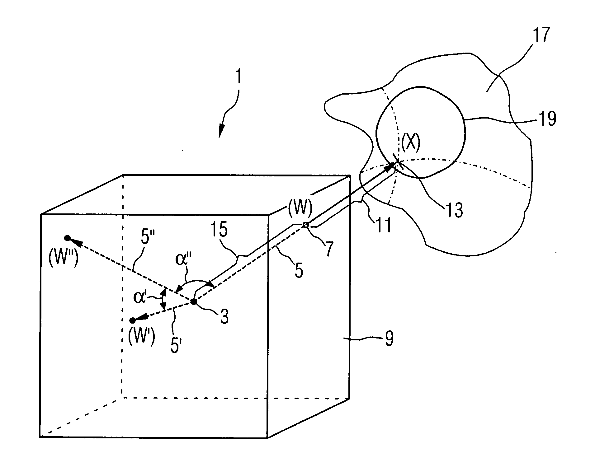
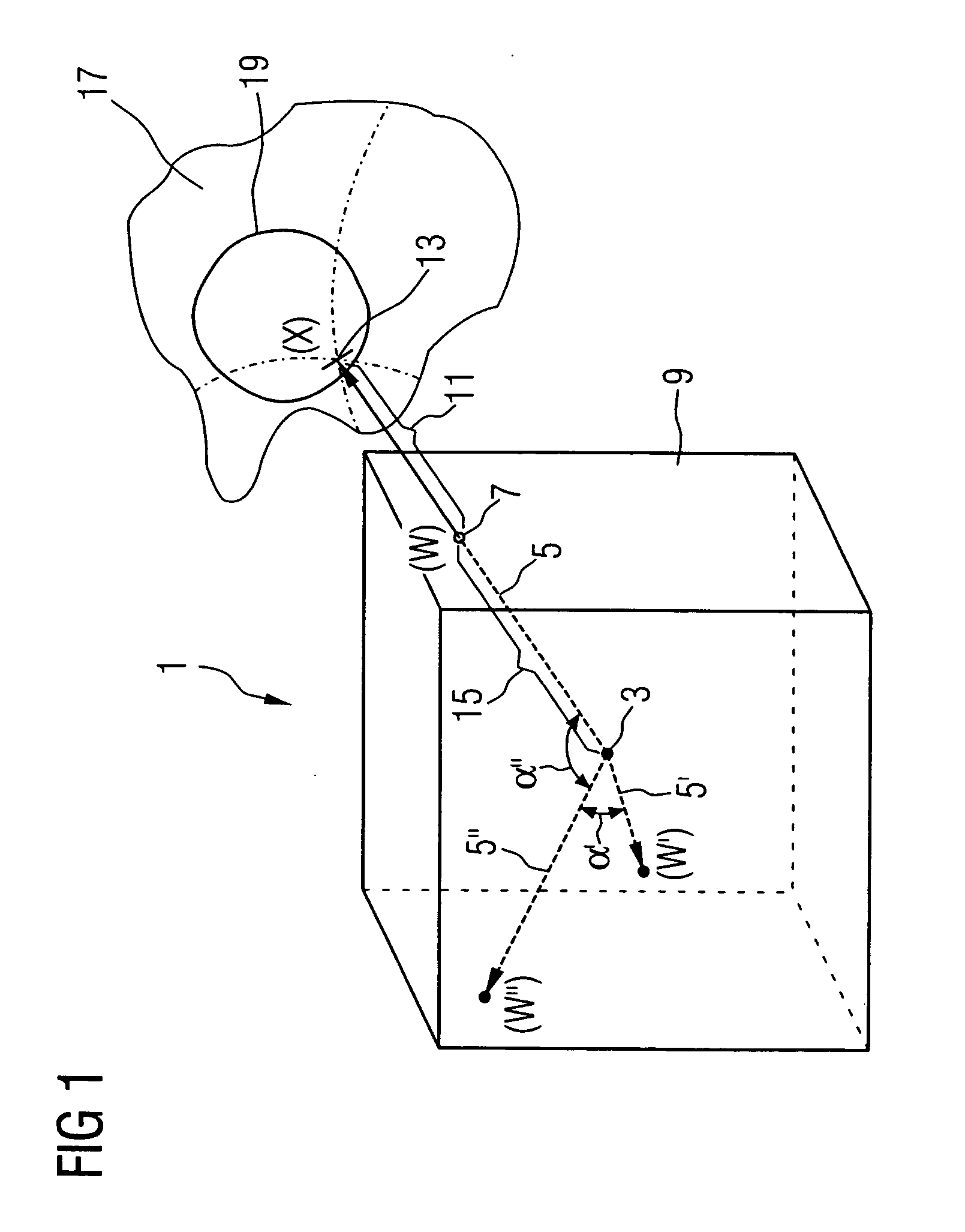
[0056]FIG. 1 schematically illustrates a procedure within the context of a particularly preferred embodiment of the method for 3D image display and processing in computed tomography using the example of the virtual endoscopy. The virtual endoscopy is intended to map a perspective view of the close surroundings of a virtual endoscope head and is used successfully for examining a colon, a bronchial tree or vessels, for example. The algorithms used for VR or SSD allow the colon wall or bronchial wall to be viewed in high quality.

[0057] For calculation, the high level of contrast difference between an air-filled interior and the surrounding tissue is utilized in this case. The VR-opacity and color functions are usually set such that the transition from intestinal, bronchial and vessel interiors to the surrounding tissue—that is to say the intestinal wall, the bronchial wall or the vessel wall—is shown opaquely. What is particularly informative and diagnostically often very important is...


PUM


Abstract

A medical imaging diagnostic method can be simultaneously simplified and improved within the context of medical 3D image display and processing. To this end, the method for medical 3D image display and processing includes prescribing an observer position, a search beam and a pixel value for a surface of a 3D evaluation volume. To simplify and improve matters, a first pixel on the search beam is determined on the basis of the pixel value. The search beam is expanded to an extended search region on the far side of the first pixel, and a second pixel on the search beam in the extended search region is determined as a pixel which is alternative or additional to the first pixel on the basis of an extended pixel value range with one or more extended pixel values. At least one of the first pixel and the second pixel is then displayed.

Description

[0001] The present application hereby claims priority under 35 U.S.C. §119 on German patent application number DE 10 2004 027 708.7 filed Jun. 7, 2004, the entire contents of which is hereby incorporated herein by reference. FIELD [0002] The invention generally relates to a method for medical 3D image display and processing. For example, the method may include steps wherein: a 3D data volume is provided, and an observer position, a search beam and a pixel value are prescribed for the 3D data volume. The invention also generally relates to a computed tomograph, to a workstation and to a computer program product. BACKGROUND [0003] Modern medical imaging methods normally provide images in digital form. To this end, the first step within the framework of “primary applications” is data recording and the provision of the digital data in the course of data construction. [0004] In particular, computed tomography images are provided in digital form and can thus be processed further directly ...

Claims


Application Information

Patent Timeline
IPC IPC(8): A61B6/03A61B5/055G06T15/08G21K1/12H05G1/60
CPCA61B6/466G06T15/08G06T2210/41
Inventor GUENDEL, LUTZ
Owner SIEMENS AG
Why Eureka
Try Eureka