[0008] When an offset or rotation angle is known, the spreader can be shifted relative to the head block by a suitable adjustment mechanism, primarily adjustment cylinders, operated by a
control unit. In other words, the spreader is slightly moved lengthwise and / or transversely and / or turned relative to the head block to compensate the offset or rotation angle as detected through a comparison of the center lines. The
edge detection and determination of an offset or rotation angle takes place immediately after the trolley has been positioned above the transport vehicle. In other words, the position of the load-carrying frame is rapidly verified and a misalignment is respectively corrected. Any positional inaccuracy can be quickly identified and corrected in a
fully automated manner because
edge detection and determination of the offset or rotation angle takes place automatically as is the adjustment of the spreader relative to the head block with the assistance of the suitable
control unit which receives respective data with respect to offset or rotation angle from the
processing unit.
[0015] According to another feature of the present invention, the
processing unit may be constructed for determining a tilt of the transport vehicle in relation to a horizontal plane. This is especially opportune, when, for example, a tire of the transport vehicle is flat or the
tire pressure is too low so that the
support surface of the transport for a container is slightly inclined. As a result, the disposition of the edge and thus the course of the center lines change, whereby the extent of the change depends on the size of the tilt angle. A potential error resulting from a tilt can thus be recognized and corrected. A tilt of the transport vehicle may, of course, also be caused by an uneven ground. If a possible
skew is known, the load center, i.e. the center of the load-carrying frame and thus also of an pendantly connected container, can be corrected by the
skew in length and transverse directions in relation to the center of the transport vehicle as well as a possible angle between the length and / or transverse lines.
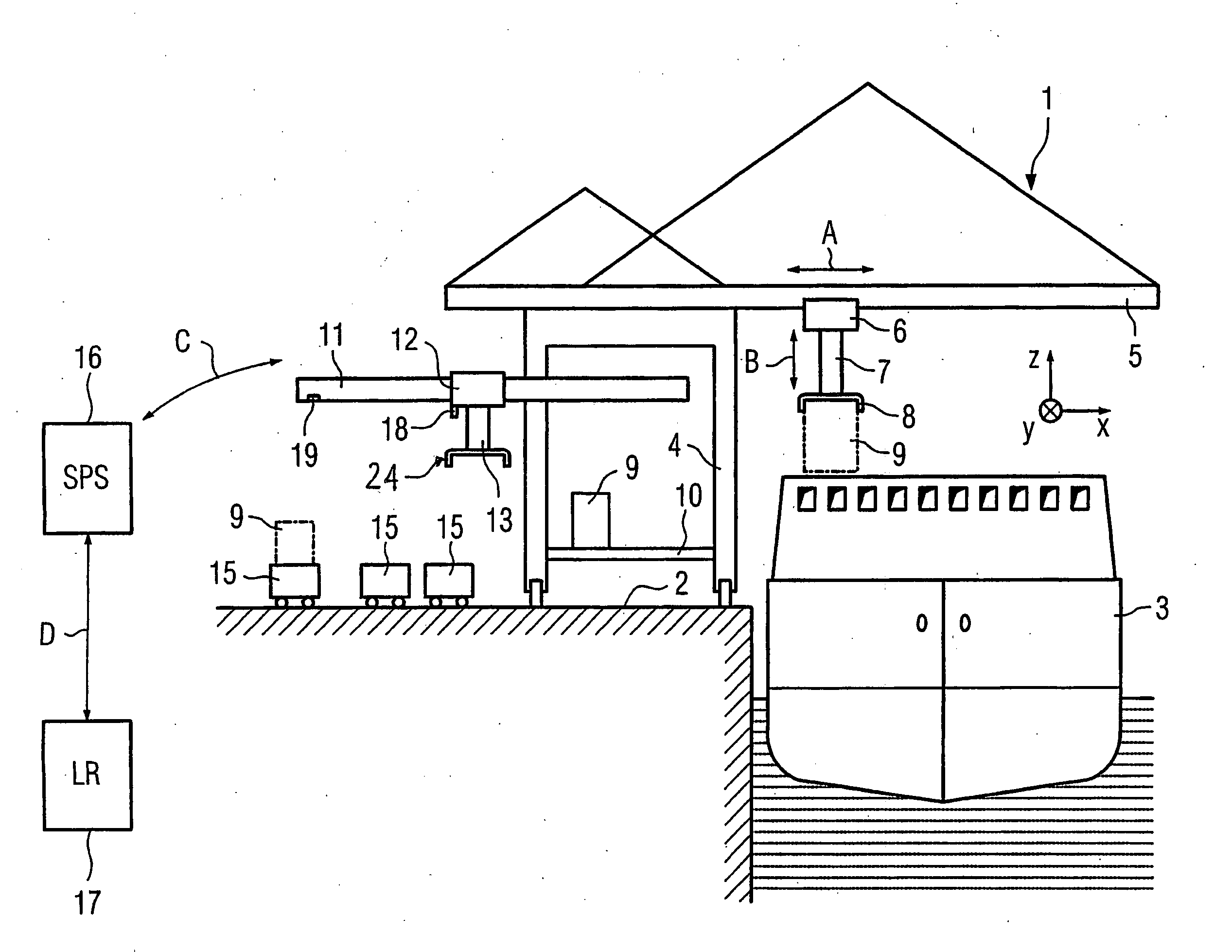
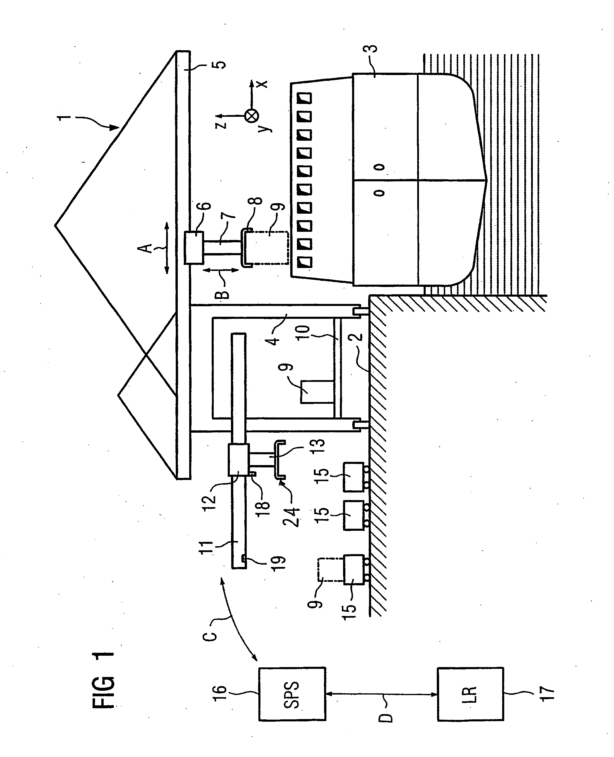
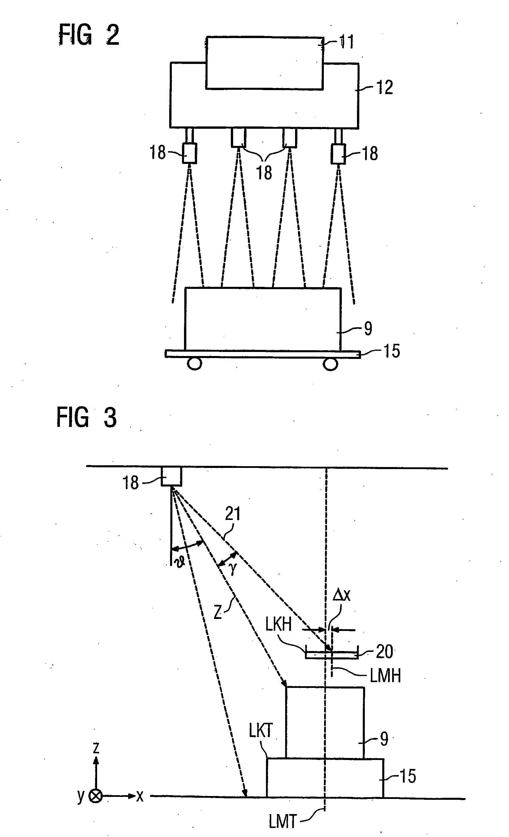
[0017] According to another feature of the present invention, each
laser scanner may be constructed to radiate a
laser beam in a cone-
beam shape at a
beam angle between 2° and 8°, especially 4°. The
laser scanners are positioned relatively high, as the trolley travels at a height of greater than 20 m, so that a large enough scanning area of the load-carrying frame is realized, when the load-carrying frame is quasi lowered through the cone-beam
radiation, and of the transport vehicle at
ground level. This ensures a continuous detection of the transverse and longitudinal edges of the load-carrying frame and the transport vehicle. Likewise, when cameras are used as detectors, the cameras can be constructed to establish also a large enough recording area.
[0018] According to another feature of the present invention, a
tilt sensor may be operatively connected to the processing unit for determining a tilt of the boom, whereby the processing unit is constructed to take into account the tilt of the boom when determining the presence of an offset between the longitudinal and transverse center lines of the head block or spreader and the longitudinal and transverse center lines of the transport vehicle, as well as the presence of a rotation angle of the center lines. The boom, along which the trolley travels, may tilt over time so that the trolley will no longer travel precisely in the horizontal plane but along a respectively inclined track. As a result, the detectors tilt as well and
record the transverse and longitudinal edges at an angle which deviates from the original calibration. In other words, the calculation of the disposition of the transverse differs. By using the
tilt sensor, a possible tilt of the boom and of the detectors can be detected and suitably compensated.
[0020] According to another feature of the present invention, a
control unit may be provided to control a hoisting operation of the trolley, whereby the control unit provides information about a lifting height of the head block or the spreader and communicates with the processing unit such that the processing unit considers the information upon determination of the possible offset and / or rotation angle. On the basis of the actual height, the processing unit is able to determine at which height information can be expected about the head block or spreader edges. By using a filter, furnished image data or image signals from the detectors, can be filtered to suppress image data artifacts or
signal artifacts in dependence on the lifting height of the head block or the spreader. For example, when an image data artifact or
signal artifact indicates the presence of an edge in a region above the actual lifting height of the head block, the indication of the edge can be ignored or simply interpreted as an error that does not require any further processing. In other words, a data or
signal filtering measure is provided that allows
elimination of error interpretations in a simple manner.

