
Breathing mask with breathing gas supply through the strap

Inactive Publication Date: 2005-12-29
DRAGERWERK AG
View PDF74 Cites 125 Cited by
  • Summary
  • Abstract
  • Description
  • Claims
  • Application Information

AI Technical Summary

Benefits of technology

[0007] The object of the present invention is to provide a breathing mask that is improved compared to the state of the art and has increased wearing comfort and increased acceptance by the user and his social environment.
[0008] The present invention is based at first on the fact that the breathing masks are fed via a specially designed strap, which considerably improves the wearing comfort. The straps, which are designed in conventional breathing masks only for absorbing the tensile forces necessary to press on the mask, are additionally used to guide the inspiratory breathing gases. The present invention comprises a breathing mask to be fastened on the head with a strap with breathing gas supply through the strap, in which the strap comprises areas that have a multilayer design and at least two layers of the material of the strap, which are located one on top of another, are connected with one another such that they form a channel, through which a gas can flow.
[0009] In an advantageous embodiment, the straps comprise an at least two-layer textile fabric, in which the layers are connected with one another such that they form longitudinally extending channels. These channels lead from the area of the mask body into the nape area of the patient. If the channel is used to feed the breathing gas, additional separate flexible tubes outside the strap for feeding the inspiratory breathing gas may be eliminated, which alone leads to a substantial improvement of the visual impression created by such a mask. It is advantageous that the layers of the material of the strap forming the channels are bonded with one another next to the particular channel. As an alternative or in addition, the connection may be brought about at the same point by sewing. Areas with one or more steps can thus be formed, as a result of which decorative effects can also be achieved with a strap according to the present invention.

Problems solved by technology

However, the wearing of breathing masks is usually linked with negative associations and is felt to be highly uncomfortable.
Moreover, the feed via the flexible tube frequently takes place via the patient's forehead, which can be felt as an accentuation of the manifestation of being dependent on a machine and, moreover, it greatly compromises recognizability in a facial area that determines the facial expressions.
The disfigurement seemingly associated with the therapy even leads to rejection of such a therapy in extreme cases.
Another problem in the acceptance of prior-art breathing masks is the nuisance associated with the generation of noise during expiration, which is due to the model of the breathing mask.
The use of individual holes as an expiration valve in or on CPAP masks leads to a locally occurring, high velocity of flow in the immediate vicinity of these holes.
This high velocity of flow turns the expiration valve into a disturbing source of noise.
Besides the generation of noise, the focusing of escaping gas flows represents an additional drawback.
A gas flow hitting the surfaces of the face, especially in the area of the patient's eyes, may be usually felt to be highly unpleasant and may lead to complaints, especially in the area of the eyes.
This increasing pneumatic resistance is felt by the patient to be very unpleasant.
However, such valves are additional complex components and they frequently cannot be mounted directly on the mask and, moreover, they produce an additional dead space.

Method used


Image

  • Breathing mask with breathing gas supply through the strap
  • Breathing mask with breathing gas supply through the strap
  • Breathing mask with breathing gas supply through the strap

Examples


Embodiment Construction

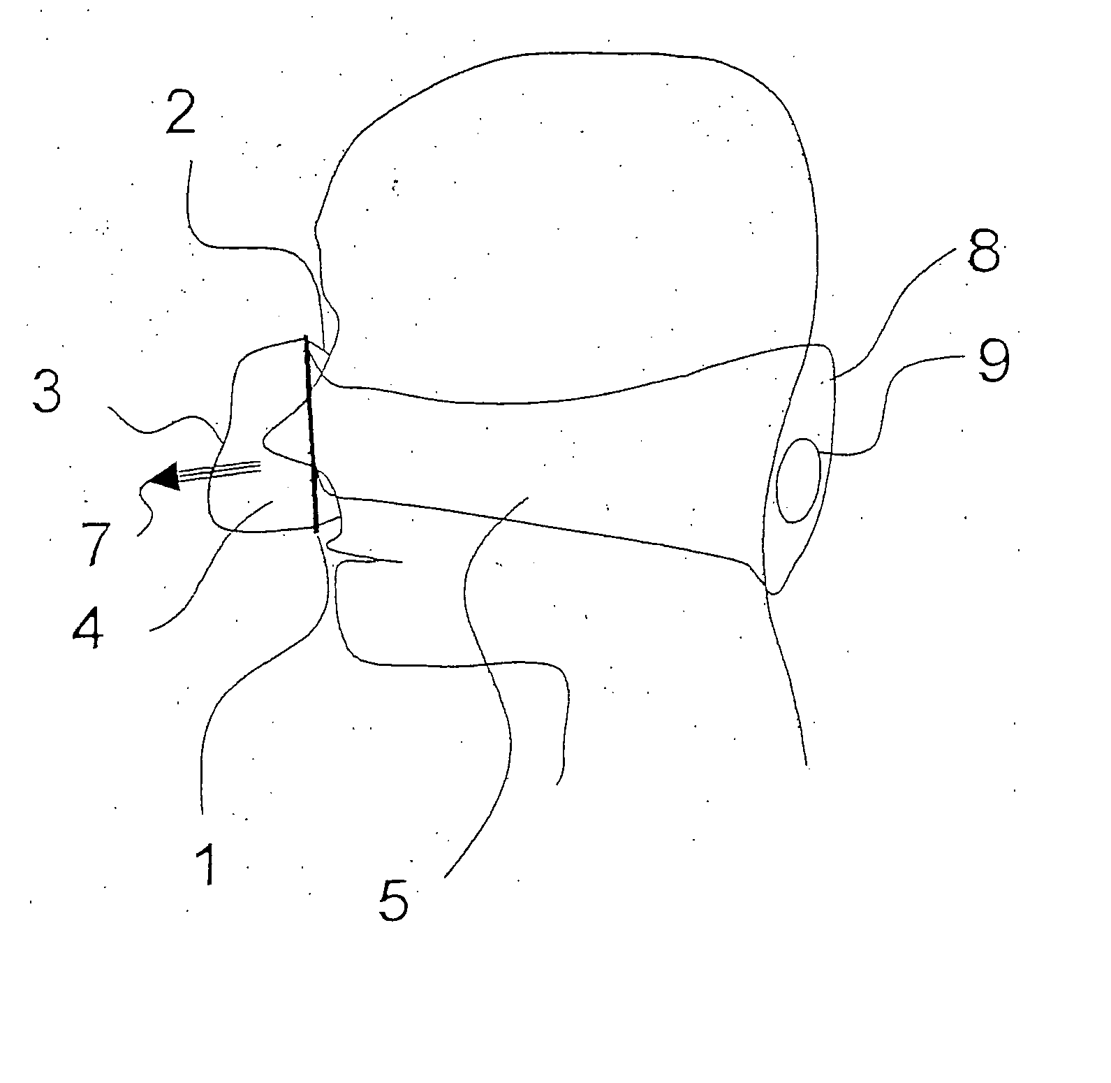
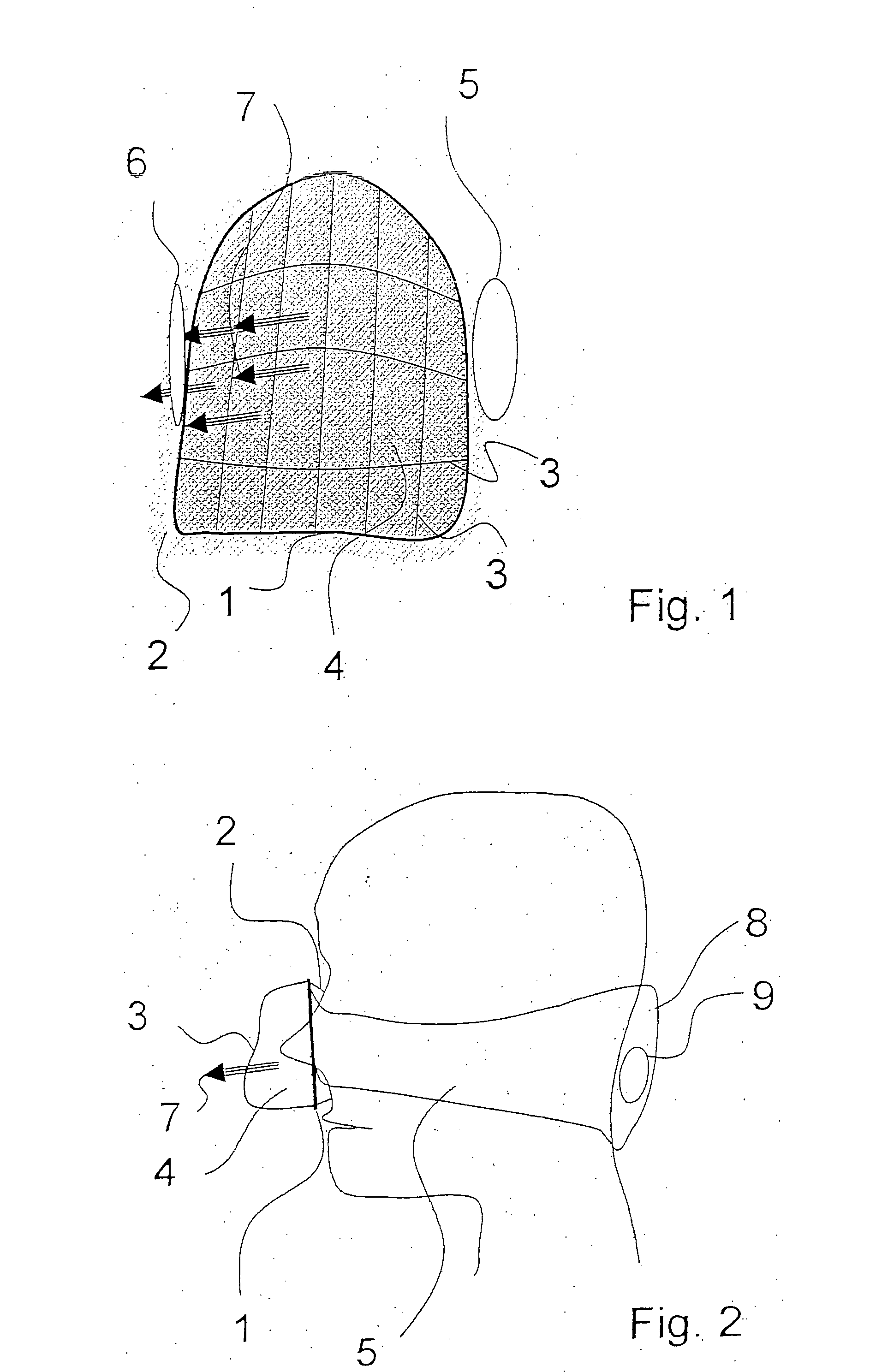
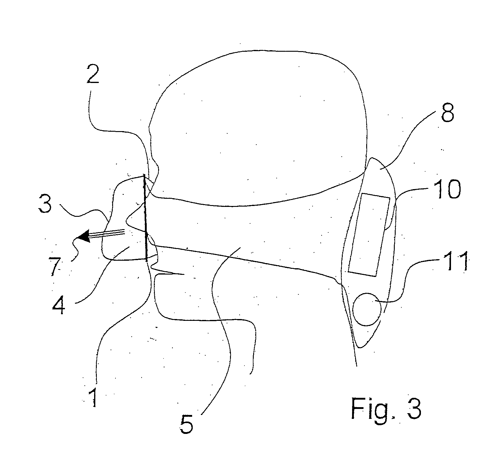
[0020] Referring to the drawings in particular, FIG. 1 shows a CPAP mask designed as a nose mask, whose mask body comprises a rigid frame 1. This frame 1 approximately defines the contact surface of the mask body on the patient's face. On the patient side, this frame 1 carries a flexible, very soft seal 2, which is supported by the internal pressure, which is provided by the CPAP respirator. On the exterior or room side, i.e., on the side facing away from the patient, the frame 1 is provided with a moldable support frame 3 in the form of a grid-like skeleton, which approximately predetermines the shape of the mask body. A nylon textile fabric 4 is mounted on this skeleton. A continuous volume flow 7, which is distributed over a very large area, which may comprise the entire surface of the mask body, is passed through the nylon fabric 4. The pneumatic resistance can be set for different conditions of use by using different mesh sizes, fabric thicknesses and a variable number of fabri...


PUM


Abstract

A breathing mask to be fastened with a strap on the head with breathing gas supply through the strap. The strap includes areas that have a multilayer design and at least two layers of the material of the strap lying one on top of another are connected with one another such that they form a channel, through which a gas can flow.

Description

CROSS REFERENCE TO RELATED APPLICATIONS [0001] This application claims the benefit of priority under 35 U.S.C. § 119 of DE 10 2004 030 068.2 filed Jun. 23, 2004, the entire contents of which are incorporated herein by reference. FIELD OF THE INVENTION [0002] The present invention pertains to a breathing mask with breathing gas supply through the strap. BACKGROUND OF THE INVENTION [0003] One application of such breathing masks is represented by so-called CPAP (continuous positive airway pressure) respirators. Patients who require respiratory support for various reasons, for example, sleep apnea or COPD (chronic obstructive pulmonary disease), are frequently treated with such CPAP respirators. A settable overpressure is now made available to the patient for supporting the respiration. The supply is usually with constant pressure over the entire breathing cycle, the set pressure being made available via a breathing mask. These breathing masks are usually designed as nose or mouth-and-n...

Claims


Application Information

Patent Timeline
IPC IPC(8): A61M16/06A62B18/02
CPCA61M16/06
Inventor MEYER, JORG-UWEKULLIK, GOTZSCHRADER, CORNELIAHANSMANN, HANS-ULLRICH
Owner DRAGERWERK AG
Learn More