Hybrid electric propulsion system and method

a hybrid electric propulsion and electric motor technology, applied in the direction of propulsion using engine-driven generators, propulsion parts, gas pressure propulsion mounting, etc., can solve the problems of reducing fuel economy, under- or over-charge of batteries,

Active Publication Date: 2005-12-29
WESTINGHOUSE AIR BRAKE TECH CORP
View PDF12 Cites 73 Cited by
  • Summary
  • Abstract
  • Description
  • Claims
  • Application Information

AI Technical Summary

Problems solved by technology

One disadvantage with the above approach is that, in case the computed state of charge is in error, the on-board energy source may not properly charge the energy storage unit, leading either to an und

Method used


Image

  • Hybrid electric propulsion system and method
  • Hybrid electric propulsion system and method
  • Hybrid electric propulsion system and method

Examples


Embodiment Construction

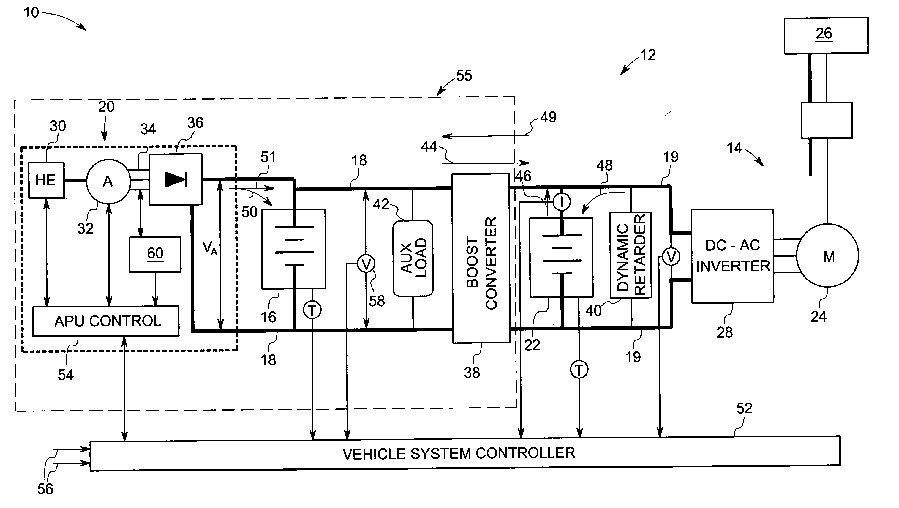
[0013] The present techniques accordingly provide an improved control for charging electrically re-chargeable energy storage units used in hybrid prolusion systems for heavy-duty vehicles such as those mentioned earlier. As described in some detail hereinafter, the present techniques can be implemented to control charging of an electrical energy storage unit (or battery) by an auxiliary power unit in a battery-battery series hybrid propulsion system, as well as by an on-board energy source in a conventional series hybrid propulsion system.

[0014] Referring now to FIG. 1, a hybrid propulsion system is illustrated, and represented generally by reference numeral 10. The illustrated configuration of the propulsion system 10 has a battery-battery hybrid series configuration. The hybrid propulsion system 10 comprises a power generation system 12 that is operable to supply power to a traction drive system 14. In addition, the power generation system 12 comprises a first energy storage unit...


PUM


Abstract

A hybrid prolusion system comprising a first energy storage unit operable to supply power to a traction drive motor. A second energy storage unit is coupled with the first energy storage unit to provide additional power on demand to the traction drive motor. An auxiliary power unit (APU) is used to charge the first battery to maintain a desired voltage across the first energy storage unit.

Description

BACKGROUND [0001] The invention relates in general to hybrid propulsion systems, and in particular to systems and methods for operating a series hybrid electric propulsion system with an auxiliary power unit. [0002] Some vehicles use electric traction motors to propel the vehicle. Typically, the electric traction motors are connected to a link, such as a bus, that provides the motors with power. One or more on-board alternators may be used to provide the power to the link. In certain operating conditions, such as when the vehicle is decelerating or is maintaining speed on a downhill grade, the back-emf produced by the electric motors is greater than the voltage provided by the engine-driven alternator. Under such conditions, the electric traction motors cease acting as motors and become generators. This process, known as dynamic braking, is a form of electric braking that is used to reduce wear on the mechanical brake system components of a vehicle. In the case where the vehicle is ...

Claims


Application Information

Patent Timeline
IPC IPC(8): B60K1/00B60L11/18B60L50/15B60L50/30B60W10/06B60W10/08B60W10/26B60W20/00
CPCB60L7/06B60L2200/26B60L7/22B60L11/123B60L11/16B60L11/1868B60W10/06B60W10/08B60W10/26B60W20/00Y02T10/6217Y02T10/6286Y02T10/7066Y02T10/7077B60L11/1881Y10S903/951Y02T90/34B60L7/14B60L50/30B60L50/61B60L58/20B60L58/30H02J7/1423H02J1/082H02J1/106H02J7/00714H02J2310/48Y02T10/62Y02T10/70Y02T90/40B60W20/13Y02T10/7072
Inventor KING, ROBERT DEANSONG, DONGWOOSALASOO, LEMBITKUMAR, AJITH KUTTANNAIR
Owner WESTINGHOUSE AIR BRAKE TECH CORP
Why Eureka
Try Eureka