Low-leakage level shifter with integrated firewall and method

a level shifting and firewall technology, applied in the field of integrated circuits and level shifting circuits, can solve the problems of increasing leakage current, small leakage current, and increasing leakage curren

Active Publication Date: 2005-12-29
MARVELL ASIA PTE LTD
View PDF3 Cites 37 Cited by
  • Summary
  • Abstract
  • Description
  • Claims
  • Application Information

AI Technical Summary

Problems solved by technology

In many cases, these advancements have come at the expense of increased leakage current.
In the past, this leakage current has been small in comparison to the total chip power; however with advancing technologies, leakage current is becoming an increasingly larger percentage.
During standby mode, many active components of one or more voltage domains are powered down; however invalid data signals generated by circuitry of a voltage domain in the standby mode may result in an increased leakage current by other circuitry.
One problem with some conventional level shifters is that invalid data signals may be generated during the standby mode causing an increase in leakage current in either the level-shifter circuitry itself and / or other circuitry.

Method used


Image

  • Low-leakage level shifter with integrated firewall and method
  • Low-leakage level shifter with integrated firewall and method
  • Low-leakage level shifter with integrated firewall and method

Examples


Embodiment Construction

[0012] The following description and the drawings illustrate specific embodiments of the invention sufficiently to enable those skilled in the art to practice the invention. Other embodiments may incorporate structural, logical, electrical, process, and other changes. Examples merely typify possible variations. Individual components and functions are optional unless explicitly required, and the sequence of operations may vary. Portions and features of some embodiments may be included in or substituted for those of others. Embodiments of the invention set forth in the claims encompass all available equivalents of those claims. Embodiments of the invention may be referred to, individually or collectively, herein by the term “invention” merely for convenience and without intending to voluntarily limit the scope of this application to any single invention or inventive concept if more than one is in fact disclosed.

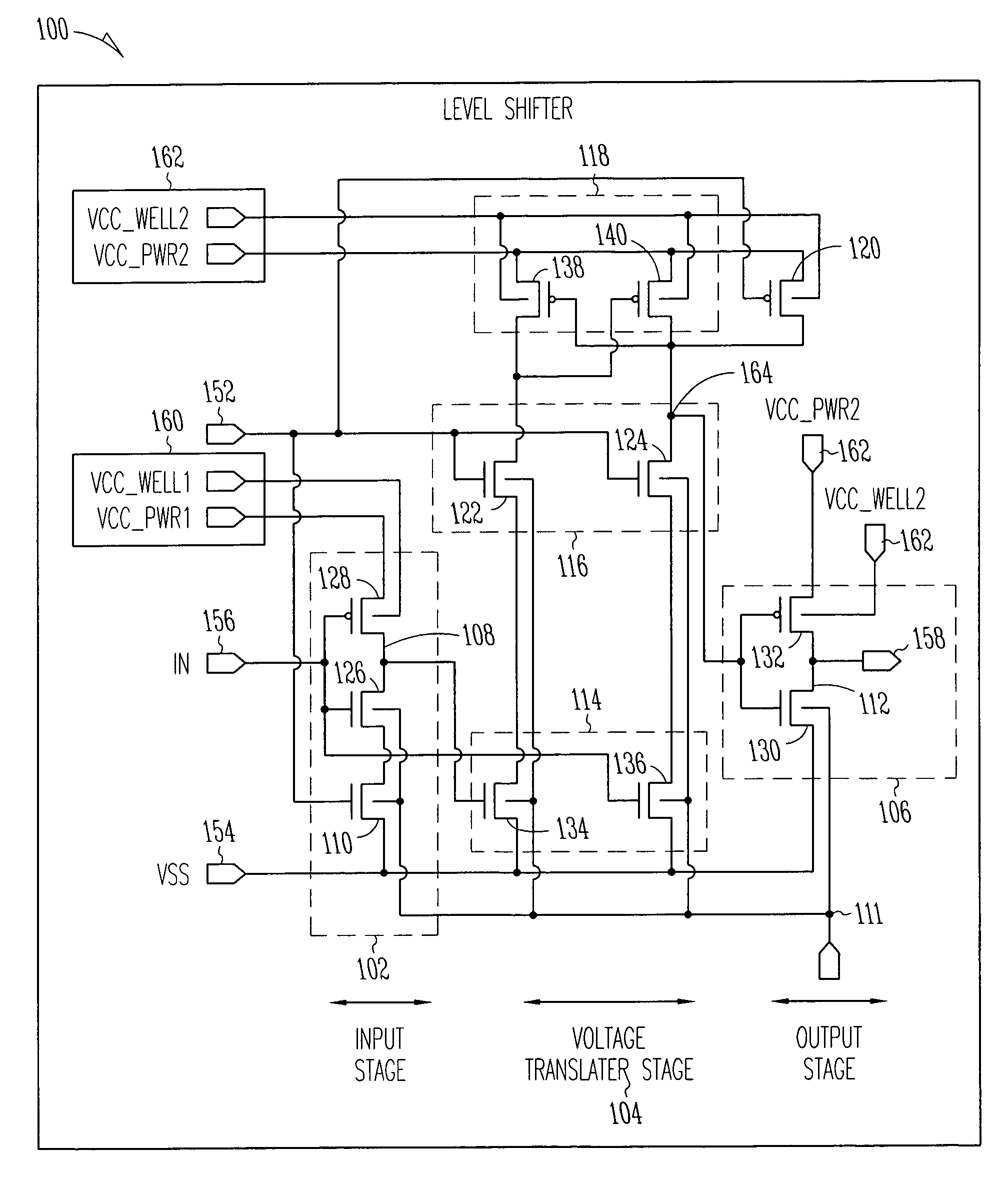
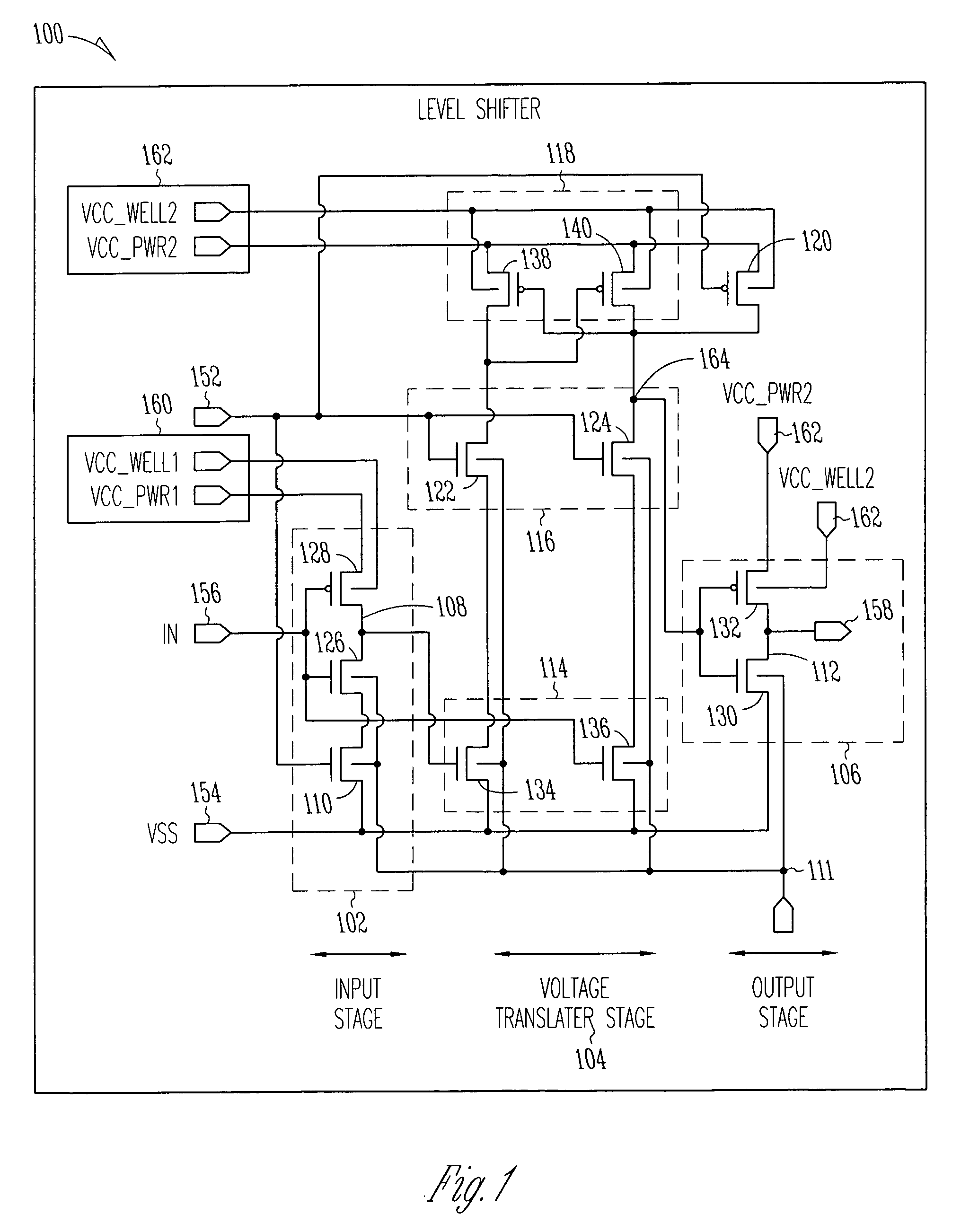
[0013]FIG. 1 is a circuit diagram of a level shifter in accordance with s...


PUM


Abstract

A level shifter may reduce leakage current and provide firewall protection between circuits of different voltage domains when one voltage domain is in a standby mode. The level shifter may either couple or decouple input circuitry from a reference voltage in response to a firewall enable signal, may translate signals between a first voltage domain and a second voltage domain when the firewall enable signal is deasserted, and may generate an output signal having a predetermined one of either a high or low state when the firewall enable signal is asserted.

Description

TECHNICAL FIELD [0001] Embodiments of the present invention pertain to electronic circuits. Some embodiments of the present invention pertain to integrated circuits and level shifting circuits. Some embodiments pertain to wireless communication devices. BACKGROUND [0002] Modern semiconductor processing technology has advanced rapidly with increased transistor density, reduced chip area and improved transistor performance. In many cases, these advancements have come at the expense of increased leakage current. In the past, this leakage current has been small in comparison to the total chip power; however with advancing technologies, leakage current is becoming an increasingly larger percentage. Part of the reason for this increase in leakage current is that many newer technologies rely more on high-leakage semiconductor devices, which may have shorter channel lengths, thinner gate-oxide layers and / or lower threshold voltages than semiconductor devices of more conventional processing ...

Claims


Application Information

Patent Timeline
Patent Type & Authority Applications(United States)
IPC IPC(8): H03K3/356H03K17/10H03K19/00H03K19/003H03K19/094
CPCH03K3/356113H03K17/102H03K19/018521H03K19/0016H03K19/00361H03K19/0013
Inventor JAHAN, MIRZA M.SARWAR, NOOR E.
Owner MARVELL ASIA PTE LTD
Why Eureka
Try Eureka