

Optical transmitter and method for transmitting optical signal
a technology of optical transmitter and optical signal, which is applied in the direction of electromagnetic transmission, transmission, and semiconductor lasers. it can solve the problems of circuit instability, loss of phase margin, and inability to greatly so as to increase the response speed of the temperature control circuit, reduce the time taken until the temperature reaches the desired temperature, and reduce the time taken
- Summary
- Abstract
- Description
- Claims
- Application Information
AI Technical Summary
Benefits of technology
Problems solved by technology
Method used
Image

Examples
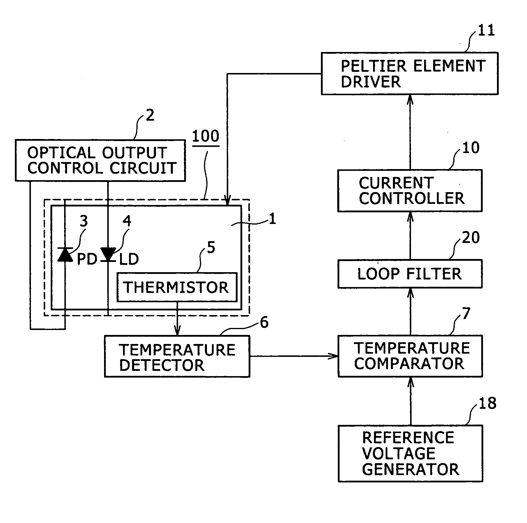
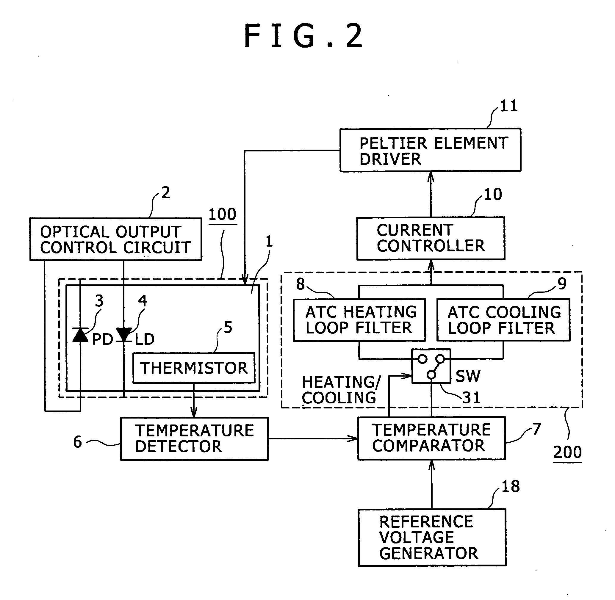
first embodiment
[0030]FIGS. 5A and 5B show the open-loop transfer characteristics of a route passing through the current controller 10, the Peltier element driver 11, the Peltier element 1, the thermistor 5 and the temperature detector 6 in the control circuit of the optical transmitter according to the In this example, FIG. 5A shows a frequency characteristic of a gain, FIG. 5B shows a frequency characteristic of a phase, with the heating time and the cooling time as parameters, respectively. Comparing the heating time with the cooling time, it is found that both of the heating time and the cooling time are different in the phase characteristic of the open loop from each other. The cooling side has such a characteristic that the phase is advanced up to 0 degree in the vicinity of 4 Hz. The transfer characteristic depends on what portion of the control circuit to be switched over. The phase characteristic is kept substantially constant at the heating side whereas the phase is changed only at the c...
second embodiment
[0037] An optical transmitter according to another embodiment of the present invention will be described with reference to FIGS. 3 and 6A, 6B. In this example, FIG. 3 is a block diagram showing the laser diode of the optical transmitter and the temperature control circuit of the laser diode according to the present invention. FIGS. 6A and 6B are graphs showing open-loop transfer characteristics of a temperature control loop from a Peltier element current controller to a thermistor voltage detector.
[0038] In the block diagram shown in FIG. 3, a detailed description of the portions described with reference to FIG. 1 or 2 will be omitted. In the optical transmitter according to this embodiment, a wavelength monitor PD 15 that monitors the intensity of a light which has passed through an etalon filter 14 is mounted on the Peltier element 1 in addition to the optical output monitor PD 3 of the LD 4. Voltages of the optical output monitor PD 3 and the wavelength monitor PD 15 are sent to ...
third embodiment
[0044] An optical transmitter according to another embodiment of the present invention will be described with reference to FIG. 4. In this example, FIG. 4 is a block diagram showing the laser diode of the optical transmitter and the temperature control circuit of the laser diode according to the present invention.
[0045] The optical transmitter according to the third embodiment combines the structure of the optical transmitter that is excellent in the stability of the optical strength as described in the first embodiment with the structure of the optical transmitter which is excellent in the stability of the oscillation wavelength as described in the second embodiment. Accordingly, in the block diagram shown in FIG. 4, a detailed description of the portions described in FIGS. 1 to 3 will be omitted. In the optical transmitter of this embodiment, the thermistor 5 for obtaining the temperature of the LD 4, the etalon filter 14 for obtaining the wavelength of the LD 4, and the wavelengt...
PUM
 Abstract
Description
Claims
Application Information