Method and apparatus for gas discharge laser output light coherency reduction

a gas discharge laser and coherency reduction technology, applied in the direction of instruments, optical radiation measurement, active medium materials, etc., can solve the problems of beam coherence and vertical symmetry

Inactive Publication Date: 2005-12-29
CYMER INC
View PDF99 Cites 57 Cited by
  • Summary
  • Abstract
  • Description
  • Claims
  • Application Information

AI Technical Summary

Problems solved by technology

Applicants have discovered that vertical symmetry can be a problem with certain laser light sources, e.g., gas discharge laser lithography light sources, ...

Method used


Image

  • Method and apparatus for gas discharge laser output light coherency reduction
  • Method and apparatus for gas discharge laser output light coherency reduction
  • Method and apparatus for gas discharge laser output light coherency reduction

Examples


Embodiment Construction

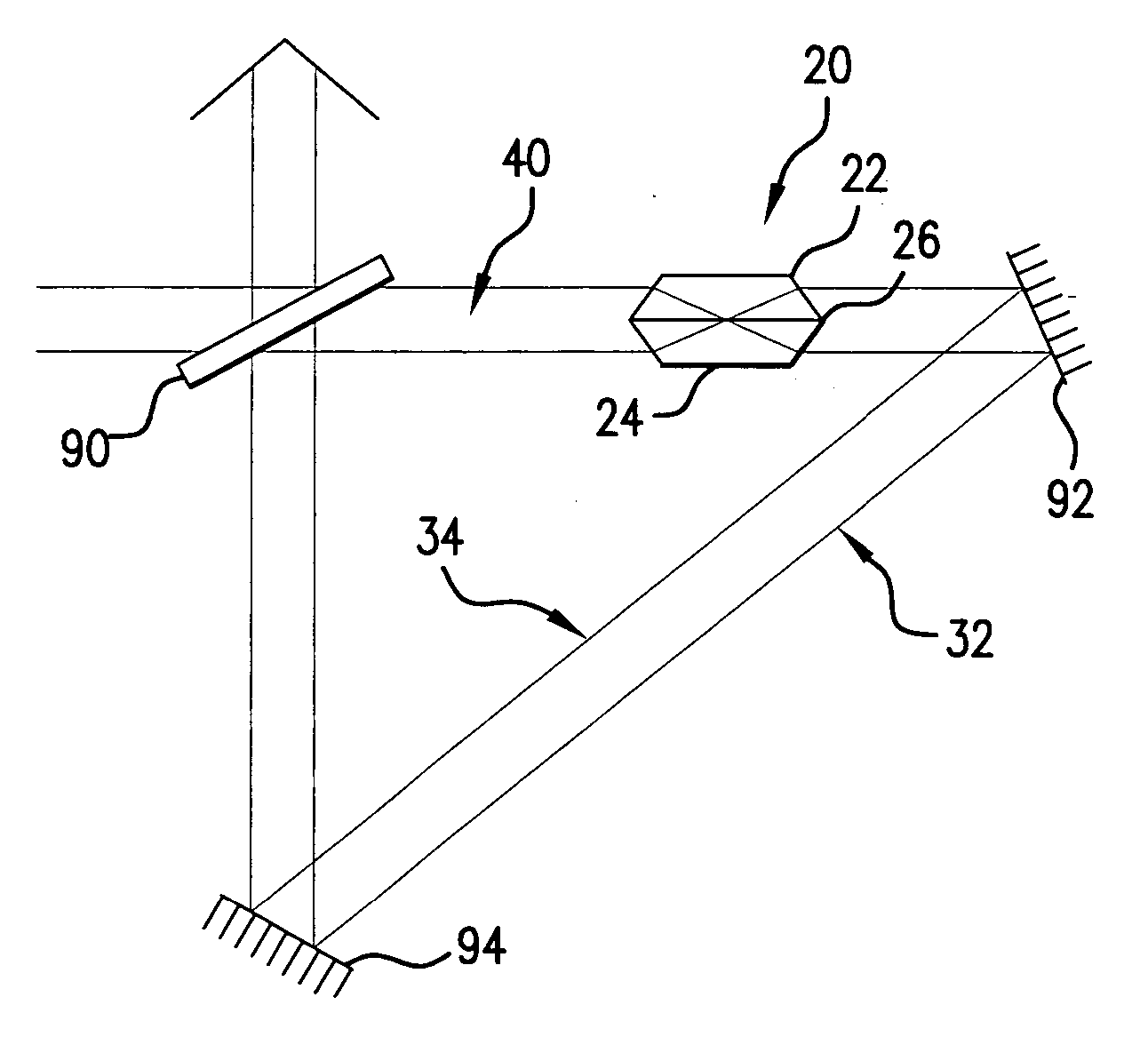
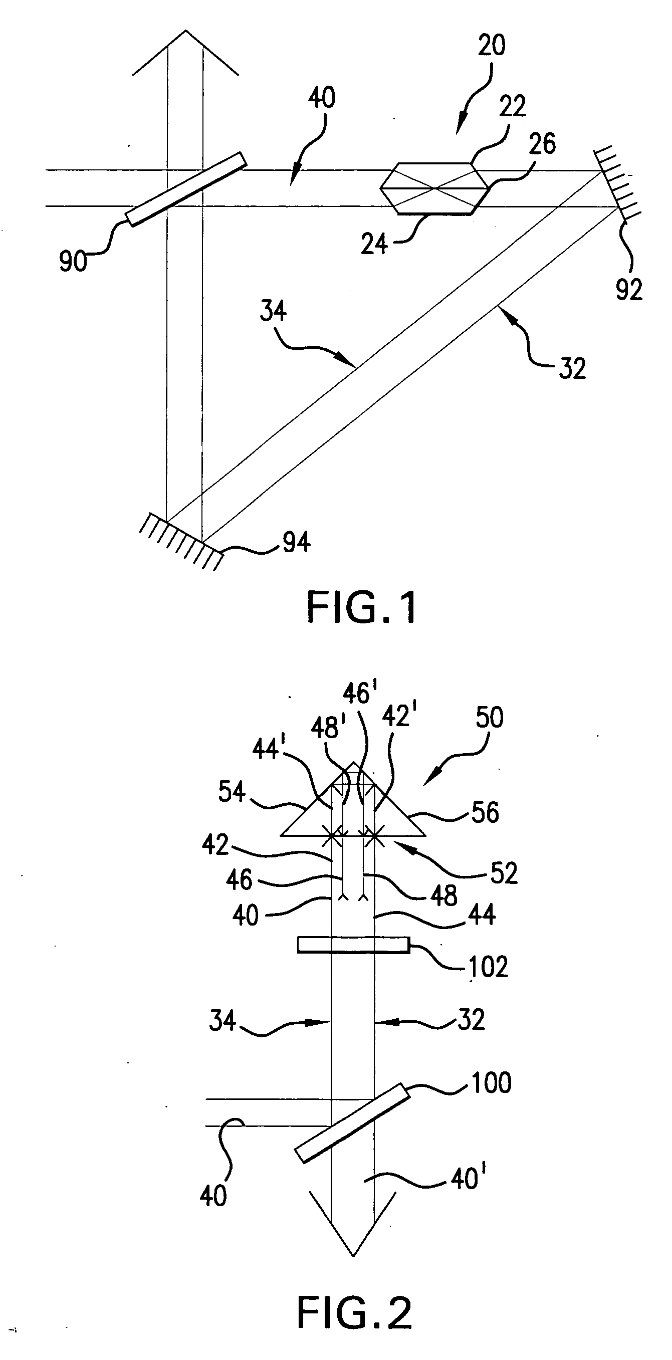
[0022] To alleviate the problem of loss of beam symmetry, e.g., vertical symmetry, e.g., where the vertical centroid tends to shift, applicants propose, e.g., the use of any of a variety of multiple optical schemes that can produce alternating inverted images of the beam. Applicants believe that such schemes will not only positively affect beam profile symmetry but also have a beneficial impact on the spatial coherence of the beam, since by there intrinsic behavior such optics can, e.g., shift the position of coherence cells.

[0023] Upon examination it was discovered by applicants in the testing of the properties of a 100 ns optical pulse stretcher (“OPuS”) as discussed in the above reference co-pending patent applications also assigned to applicants' assignee, that beam symmetry can be improved when optics such as those contained in an OPuS module are inserted into the laser output beam path. This effect was attributed by applicants to the imaging characteristics of, e.g., the opti...


PUM


Abstract

A method and apparatus for producing with a gas discharge laser an output laser beam comprising output laser light pulses, for delivery as a light source to a utilizing tool is disclosed which may comprise a beam path and a beam homogenizer in the beam path. The beam homogenizer may comprise at least one beam image inverter or spatial rotator, which may comprise a spatial coherency cell position shifter. The homogenizer may comprise a delay path which is longer than, but approximately the same delay as the temporal coherence length of the source beam. The homogenizer may comprise a pair of conjoined dove prisms having a partially reflective coating at the conjoined surfaces of each, a right triangle prism comprising a hypotenuse face facing the source beam and fully reflective adjoining side faces or an isosceles triangle prism having a face facing the source beam and fully reflective adjoining side faces or combinations of these, which may serve as a source beam multiple alternating inverted image creating mechanism. The beam path may be part of a bandwidth measuring the bandwidths of an output laser beam comprising output laser light in the range of below 500 femtometers at accuracies within tens of femtometers. The homogenizer may comprise a rotating diffuser which may be a ground glass diffuser which may also be etched. The wavemeter may also comprise a collimator in the beam path collimating the diffused light; a confocal etalon creating an output based upon the collimated light entering the confocal etalon; and a detector detecting the output of the confocal etalon and may also comprise a scanning mechanism scanning the angle of incidence of the collimated light entering the confocal etalon which may scan the collimated light across the confocal etalon or scan the etalon across the collimated light, and may comprise an acousto-optical scanner. The confocal etalon may have a free spectral range approximately equal to the E95 width of the beam being measured. The detector may comprise a photomultiplier detecting an intensity pattern of the output of the confocal etalon.

Description

RELATED CASES [0001] The present application is related to co-pending U.S. application Ser. No. 10 / 676,175, filed on Sep. 30, 2003, entitled GAS DISCHARGE MOPA LASER SPECTRAL ANALYSIS MODULE, Attorney Docket No. 2002-0092-01, and Ser. No. 10 / 615,321, filed on Sep. 30, 2003, entitled OPTICAL BANDWIDTH METER FOR LASER LIGHT, Attorney Docket No. 2003-0002-01, and Ser. No. 10 / 615,321, filed on Jul. 7, 2003, entitled OPTICAL BANDWIDTH METER FOR VERY NARROW BANDWIDTH LASER EMITTED LIGHT, Attorney Docket No. 2003-0004-01, and Ser. No. 10 / 609,223, filed on Jun. 26, 2003, entitled METHOD AND APPARATUS FOR MEASURING BANDWIDTH OF AN OPTICAL OUTPUT OF A LASER, Attorney Docket No. 2003-0056-01, and Ser. No. 10 / 739,961 filed on Dec. 17, 2003, entitled GAS DISCHARGE LASER LIGHT SOURCE BEAM DELIVERY UNIT, Attorney Docket No. 2003-0082-01, and Ser. No. 10 / 676,224, filed on Sep. 30, 2003, entitled OPTICAL MOUNTINGS FOR GAS DISCHARGE MOPA LASER SPECTRAL ANALYSIS MODULE, attorney Docket No. 2003-0088-0...

Claims


Application Information

Patent Timeline
IPC IPC(8): G01J1/42G01J3/02G01J3/12G01J3/26G01J9/02G02B5/04G02B5/28G02B27/48G03F7/20H01S3/00H01S3/08H01S3/22
CPCG01J1/4257H01S3/005G01J3/0205G01J3/027G01J3/0291G01J3/0297G01J3/1256G01J3/26G01J9/02G01J2009/0249G01J2009/0257G02B5/04G02B5/284G02B27/48G03F7/70025G03F7/70583G01J3/02
Inventor RAFAC, ROBERT J.SMITH, SCOT T.
Owner CYMER INC
Why Eureka
Try Eureka