Polymer electrolyte fuel cell and power generation device

a fuel cell and polymer electrolyte technology, applied in the field of moisture distribution within a polymer electrolyte fuel cell, can solve the problems of inability to completely prevent undesirable phenomena in power generation function, inability to transfer insufficient amount of moisture from the moist portion to the dry portion, and difficulty in completely preventing undesirable phenomena in the power generation function. to achieve the effect of improving the transporting performance of moistur

Inactive Publication Date: 2005-12-29
NISSAN MOTOR CO LTD
View PDF3 Cites 14 Cited by
  • Summary
  • Abstract
  • Description
  • Claims
  • Application Information

AI Technical Summary

Benefits of technology

[0006] It is therefore an object of this invention to improve the transporting performance of moisture from a m

Problems solved by technology

Therefore, a sufficient amount of moisture cannot be transferred from the moist portion to the dry portion if the moisture transporting distance between the two portions is long, and there is a possibility that the moist state of the membrane electrode assembly (MEA) cannot be made uniform.
For this reason, it

Method used


Image

  • Polymer electrolyte fuel cell and power generation device
  • Polymer electrolyte fuel cell and power generation device
  • Polymer electrolyte fuel cell and power generation device

Examples


second embodiment

[0077] Referring to FIGS. 10 to 14, this invention will be described.

first embodiment

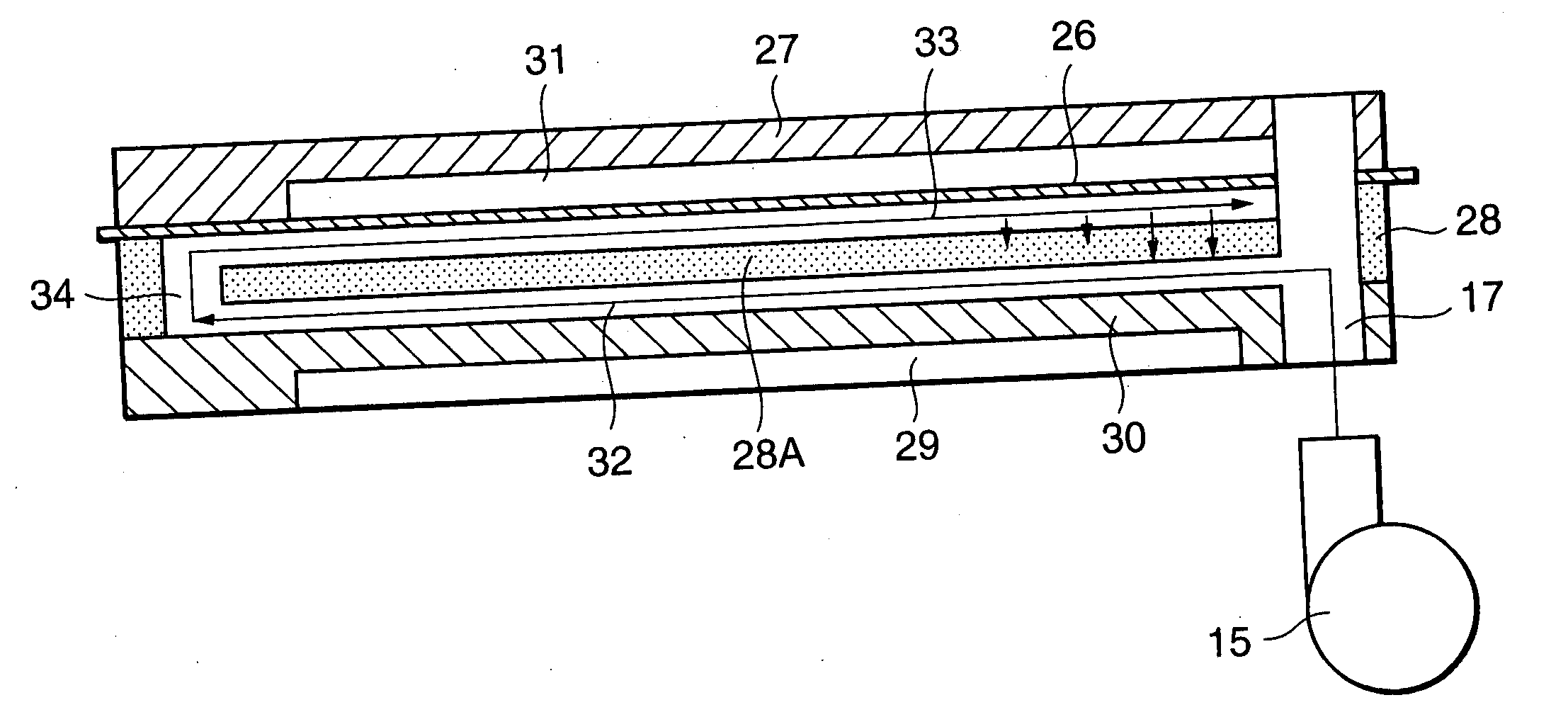
[0078] The power generation device shown in FIG. 10 differs from that of the first embodiment in the structure of the cathode gas supply unit 3. The upstream cathode gas channel 32 of each fuel cell is connected to an external pipe 39A that leads to a blower 38 outside of the fuel cell stack 1 through a second outlet manifold 36. The blower 38 takes in the cathode gas of the external pipe 39A and forcibly sends out the cathode gas to an external pipe 39B. The cathode gas that is sent out to the external pipe 39B is redistributed to the downstream cathode gas channel 33 of each of the fuel cells through a second inlet manifold 37 that is formed in the fuel cell stack 1.

[0079] Referring to FIG. 11, the second outlet manifold 36 that communicates with the upstream cathode gas channel 32, and the second inlet manifold 37 that communicates with the downstream cathode gas channel 33 are formed in the porous BPP 28 as substitutes for the through hole 34. As shown in FIG. 12, the second out...

third embodiment

[0086] Referring to FIG. 15, this invention will be described.

[0087] In this embodiment, the cross sectional area of the outlet manifold 18 is set larger than the cross sectional area of the inlet manifold 17, and the cross sectional area of the second inlet manifold 37 is set larger than the cross sectional area of the second outlet manifold 36. Other structures are identical to those of the second embodiment.

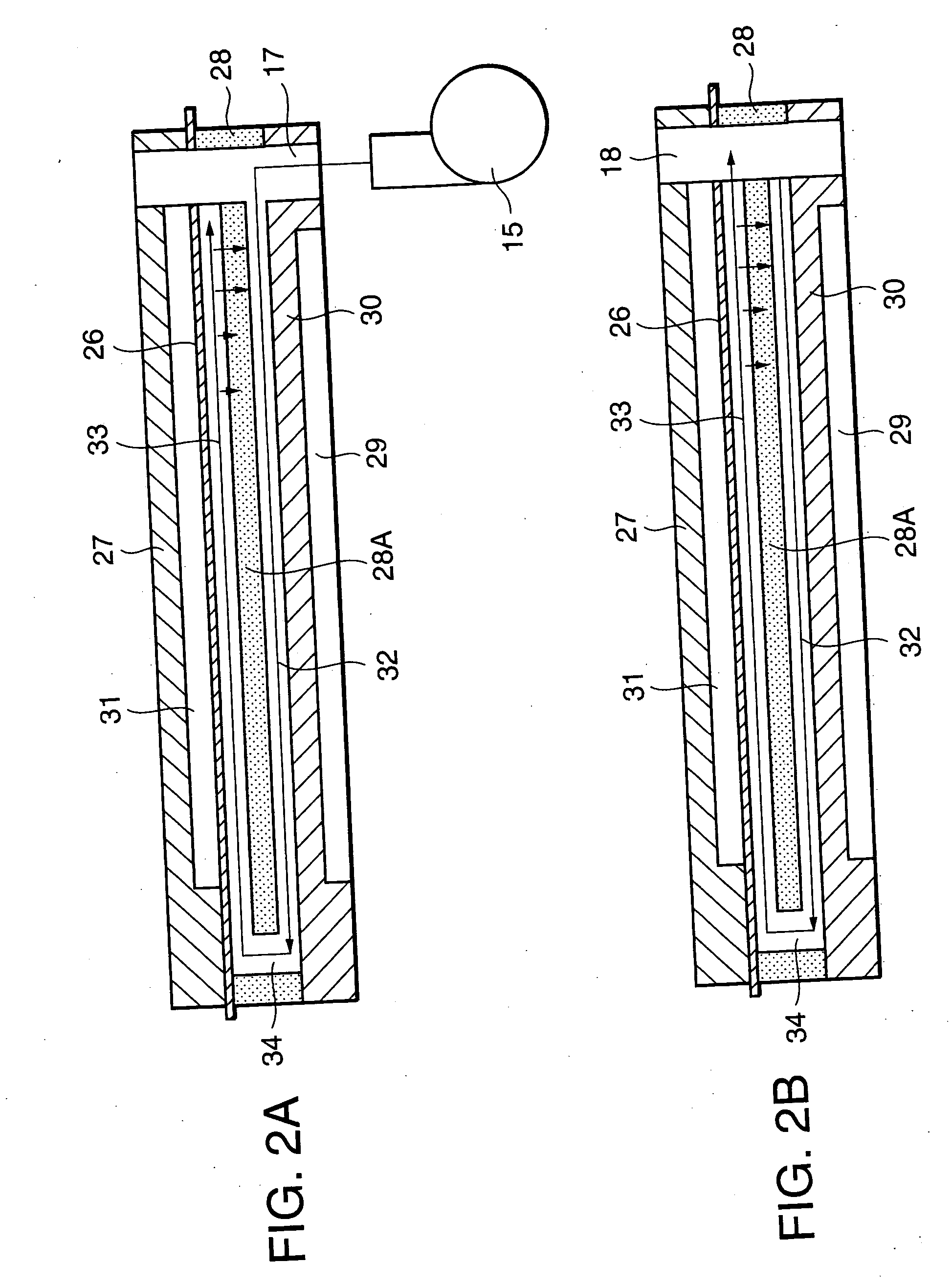
[0088] The MEA 26 faces only the downstream cathode gas channel 33 of the porous BPP 28, and does not face the upstream cathode gas channel 32. Therefore, it is necessary to make the flow of the cathode gas uniform in the downstream cathode gas channel 33, but it is not necessary to do so in the upstream cathode gas channel 32.

[0089] The widths of the cross section of the outlet manifold 18, which serves as an outlet of the downstream cathode gas channel 33, and the cross section of the second inlet manifold 37, which serves as an inlet of the downstream cathode gas channel ...


PUM


Abstract

A fuel cell is provided with a membrane electrode assembly (26) in which an anode (26B) and a cathode (26C) are formed on both sides of a polymer electrolyte film (26A). The fuel cell is provided with a downstream gas supply channel (33) facing the cathode (26C), an upstream gas supply channel (32) through which a cathode gas is supplied to the downstream gas supply channel (33) and which does not face the cathode (26C), and a partition wall (28A) which is made from a porous material and partitions the downstream gas supply channel (33) and the upstream gas supply channel (32). Electro-chemical reactions of the cathode gas in the cathode (26C) generates a large amount of moisture. The moisture passes through the partition wall (26A) and humidifies the cathode gas of the upstream gas supply channel (32), thereby making the moisture distribution in the membrane electrode assembly (26) uniform.

Description

FIELD OF THE INVENTION [0001] This invention relates to moisture distribution within a polymer electrolyte fuel cell (PEFC). BACKGROUND OF THE INVENTION [0002] Tokkai Hei 8-138691, published by Japan Patent Office in 1996, discloses a moisture transporting structure of a polymer electrolyte fuel cell (PEFC). The polymer electrolyte fuel cell (PEFC) is provided with a membrane electrode assembly (MEA) in which a polymer electrolyte film is sandwiched by gas diffusion electrodes (GDEs) that constitute an anode and a cathode. The membrane electrode assembly (MEA) is gripped by a pair of plates. Gas channels facing the cathode and the anode, respectively, are formed in the plates. [0003] The membrane electrode assembly (MEA) generates a large amount of water vapor as a result of a reaction between hydrogen ions and oxygen in the gas diffusion electrodes (GDEs). On the other hand, in order for the membrane electrode assembly (MEA) to separate hydrogen into protons and hydrogen ions neede...

Claims


Application Information

Patent Timeline
IPC IPC(8): H01M8/04H01M8/06H01M8/10H01M8/02H01M8/24
CPCH01M8/0228H01M8/0247H01M8/04029Y02E60/50H01M8/04291H01M8/2415H01M2008/1095H01M8/04119H01M8/2483H01M8/0267H01M8/0263H01M8/2484H01M8/0258H01M8/04H01M8/02
Inventor IKEZOE, KEIGO
Owner NISSAN MOTOR CO LTD
Why Eureka
Try Eureka