High resolution DNA detection methods and devices
a dna detection and high-resolution technology, applied in the field of high-resolution dna detection methods and devices, can solve the problems of high system costs, and ineffective gene chip systems
- Summary
- Abstract
- Description
- Claims
- Application Information
AI Technical Summary
Benefits of technology
Problems solved by technology
Method used
Image
Examples
example 1
Preparation of a Sample to Detect Pathogens
[0082] A sample to be tested is isolated. A common sample would be a blood sample from a patient. The sample is injected into the device. The sample moves into a chamber where it is treated chemically, with detergents, and enzymatically, with proteases to free nucleic acid molecules from cells in the sample. Heat treatment is also used to facilitate the release of the nucleic acid molecules. For that reason, proteins used in the present invention are preferably thermostable. The mixture may then pass though a filter on the chip to partially purify the nucleic acid molecules.
example 2
Preparation of Oligonucleotide Probe Sets
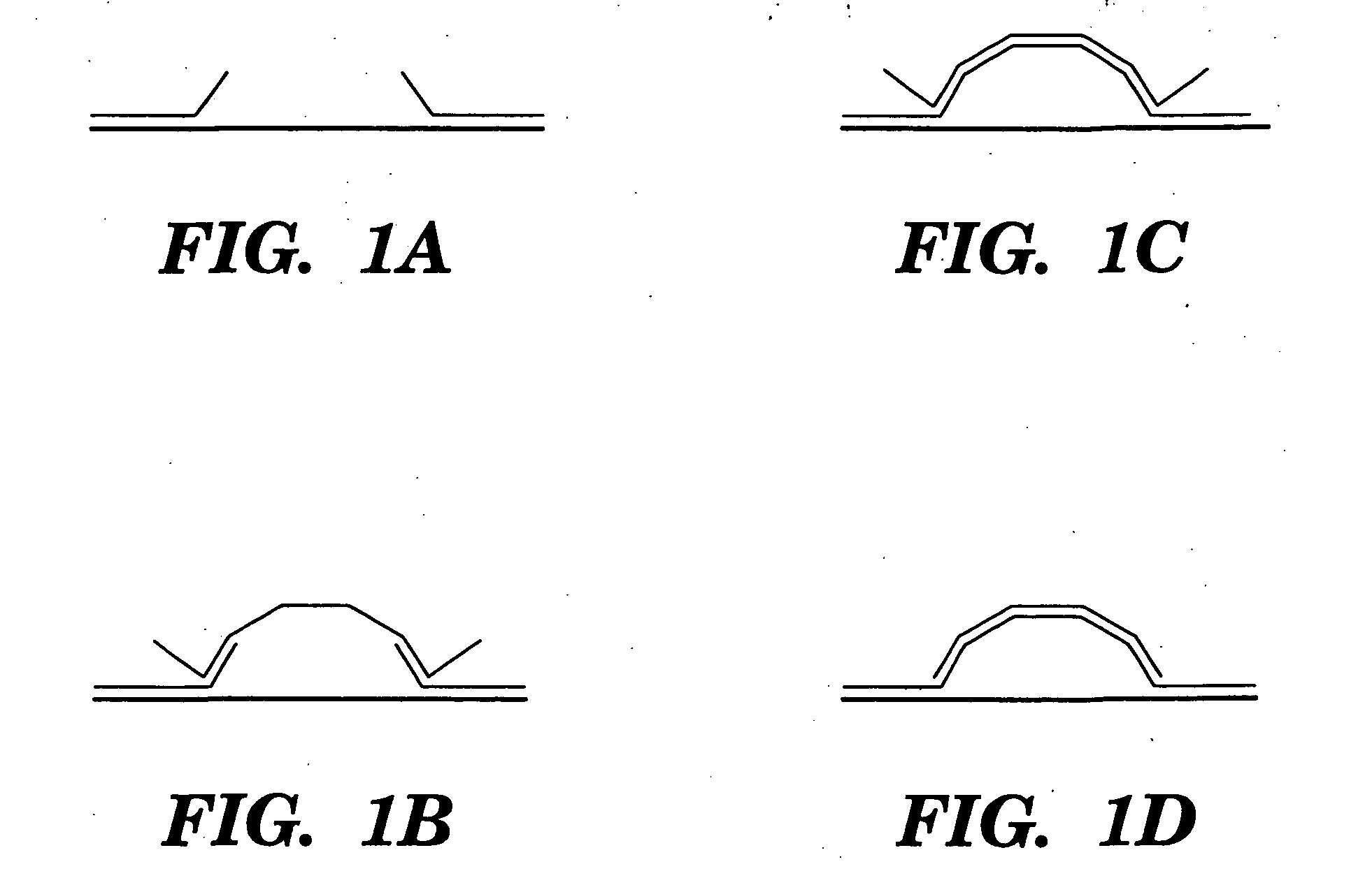
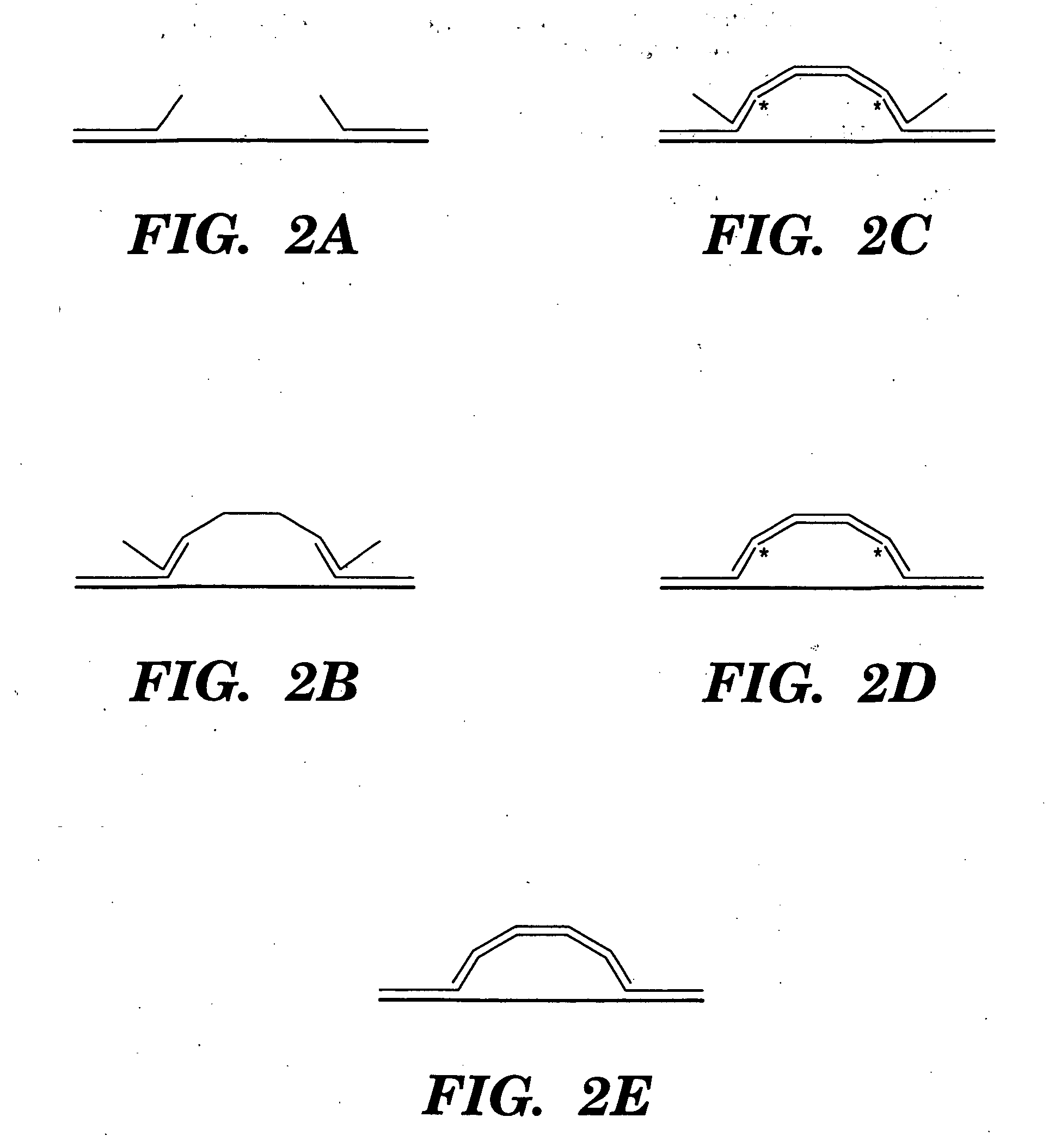
[0083] Each oligonucleotide probe set is selected so that the two probes are complimentary to a portion of the target nucleic acid molecule and so that the two portions of the target nucleic acid molecule are located sufficiently far apart that the nucleic acid molecule can bridge the gap between the two probes on the device when they are both bound. The complimentary sequences will be chosen such that there is some additional length to allow the target nucleic acid molecule to move freely when bound by one probe, so that it may access the second probe. Preferably the molecule will not be much longer than needed to easily bridge the gap. As the length of the molecule increases the chance of it locating the second probe decreases, because the effective concentration of the binding site on the target molecule decreases as the volume in which it can move increases.
[0084] Each probe set will be attached to a substrate so that they are positione...
example 3
Testing for the Presence of the Target Nucleic Acid Molecule
[0085] The probe sets will be contacted with the nucleic acid molecules. The test chamber has a small volume to facilitate binding of the target to the probe. To increase the chance of binding, the sample is circulated multiple times through the test chamber. The sample will flow through a test chamber containing the probe sets, at a flow rate sufficiently low to allow the target nucleic acid molecules to bind to a probe. Conditions are determined by the length and sequence of the probe.
[0086] The conditions will be set at a level where the stringency is sufficient to eliminate non-specific binding to the probes. The target nucleic acid molecule is contacted with the probes under stringent conditions. The stringent conditions for hybridization are by the nucleic acid, salt, and temperature. These conditions are well known in the art and may be-altered in order to identify or detect identical or related polynucleotide sequ...
PUM
| Property | Measurement | Unit |
|---|---|---|
| Temperature | aaaaa | aaaaa |
| Electrical conductor | aaaaa | aaaaa |
| Thermal stability | aaaaa | aaaaa |
Abstract
Description
Claims
Application Information
 - R&D
- Intellectual Property
- Life Sciences
- Materials
- Tech Scout
- Unparalleled Data Quality
- Higher Quality Content
- 60% Fewer Hallucinations
Browse by: Latest US Patents, China's latest patents, Technical Efficacy Thesaurus, Application Domain, Technology Topic, Popular Technical Reports.
© 2025 PatSnap. All rights reserved.Legal|Privacy policy|Modern Slavery Act Transparency Statement|Sitemap|About US| Contact US: help@patsnap.com


