

Methods of forming patterned photoresist layers over semiconductor substrates
- Summary
- Abstract
- Description
- Claims
- Application Information
AI Technical Summary
Benefits of technology
Problems solved by technology
Method used
Image

Examples
Embodiment Construction
[0024] This disclosure of the invention is submitted in furtherance of the constitutional purposes of the U.S. Patent Laws “to promote the progress of science and useful arts” (Article 1, Section 8).
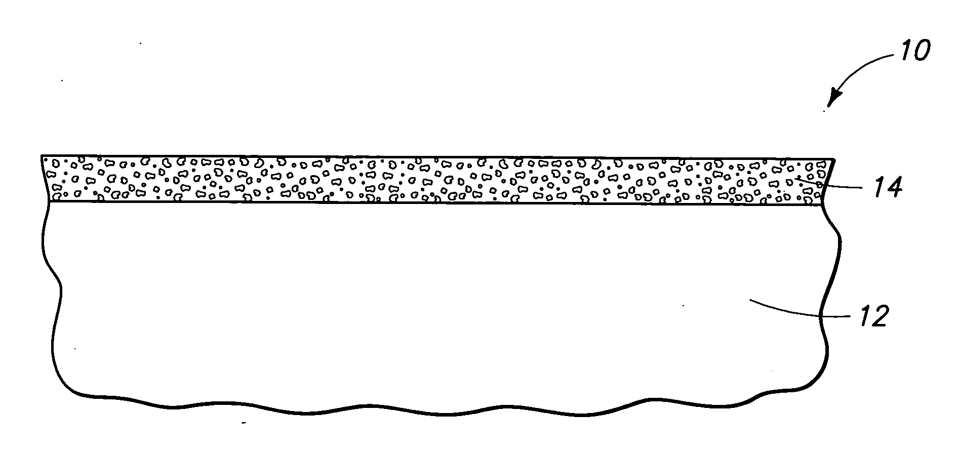
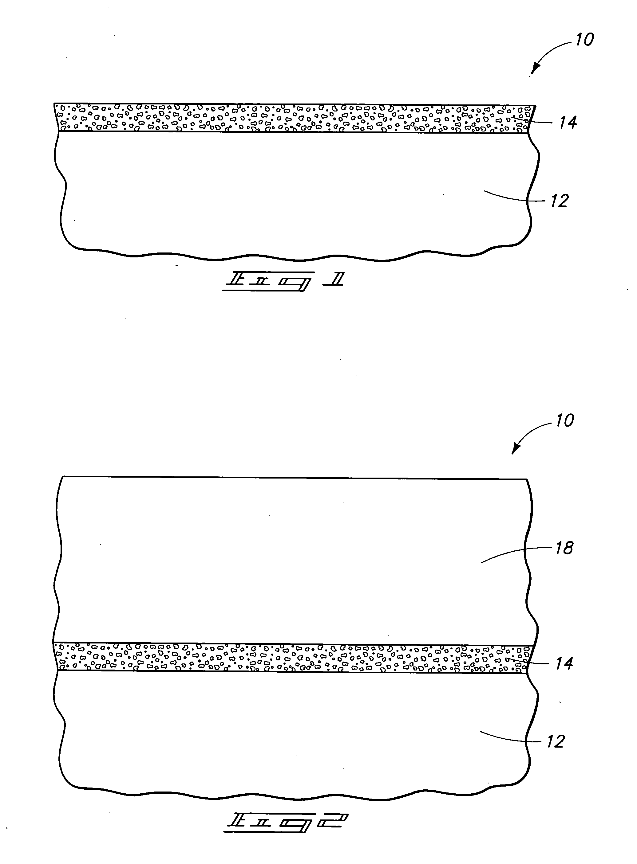
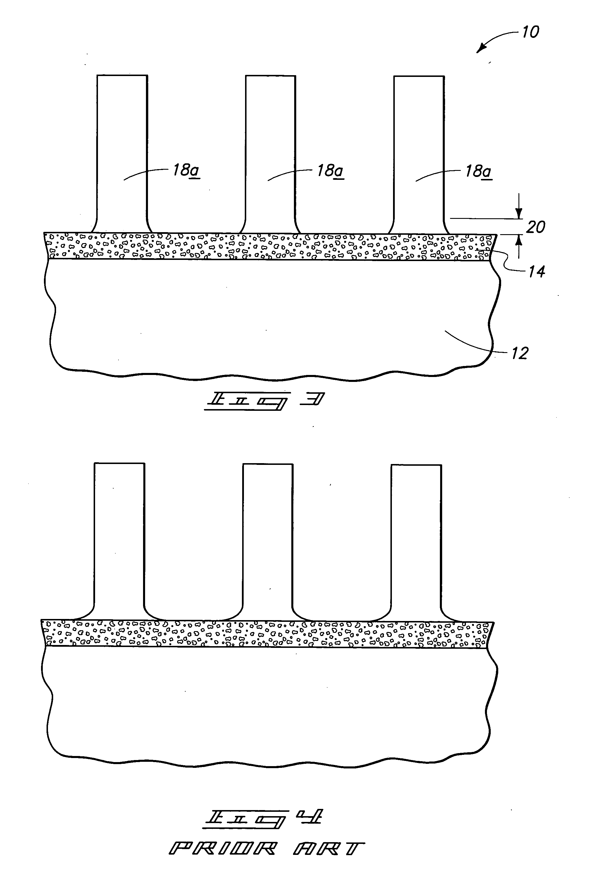
[0025] A method of forming a patterned photoresist layer over a semiconductor substrate is described initially with reference to an exemplary embodiment as depicted in FIGS. 1-3. Referring initially to FIG. 1, a wafer fragment 10 comprises a semiconductor substrate 12. In the context of this document, the term “semiconductor substrate” or “semiconductive substrate” is defined to mean any construction comprising semiconductive material, including, but not limited to, bulk semiconductive materials such as a semiconductive wafer (either alone or in assemblies comprising other materials thereon), and semiconductive material layers (either alone or in assemblies comprising other materials). The term “substrate” refers to any supporting structure, including, but not limited to, the semiconduc...
PUM
 Abstract
Description
Claims
Application Information