Devices and methods for controlling expandable prosthesis during develoyment

Inactive Publication Date: 2005-12-29
XTENT INC
View PDF99 Cites 393 Cited by
  • Summary
  • Abstract
  • Description
  • Claims
  • Application Information

AI Technical Summary

Benefits of technology

[0007] The present invention provides prostheses, prosthesis delivery systems, and methods of prosthesis deployment that enable the precise and controllable delivery of multiple prostheses using a single delivery catheter. The prostheses, delivery systems, and methods of the invention provide for the precise control of prosthesis placement so that inter-prosthesis spacing is maintained at a constant and optimum distance. In some embodiments, both axial and rotational displacement of the prostheses relative to the delivery catheter is controlled during deployment, enabling the delivery of multiple prostheses that interleave with one another without overlap. The prostheses, prosthesis delivery systems, and methods of the invention further enable th

Problems solved by technology

While self-expanding stents have demonstrated promise in various applications, such stents face a number of challenges.
One such challenge is that in some cases the disease in a vessel may be so extensive that a stent of very long length, e.g. 30-200 mm, is called for.
Currently available stents are typically less than 30 mm in length, and suffer from excessive stiffness if made longer.
Such stiffness is particularly problematic in peripheral vessels such as the femoral arteries, where limb movement requires a high degree of flexibility in any stent implanted in such vessels.
However, this approach has suffered from several drawbacks.
In order to place multiple stents, multiple catheters must be inserted, removed and exchanged, heightening risks, lengthening procedure time, raising costs, and causing excessive material waste.
In addition, the deployment of multiple stents end-to-end suffers from the inability to accurately control stent placement and the spacing between stents.
This results i

Method used


Image

  • Devices and methods for controlling expandable prosthesis during develoyment
  • Devices and methods for controlling expandable prosthesis during develoyment
  • Devices and methods for controlling expandable prosthesis during develoyment

Examples


Example

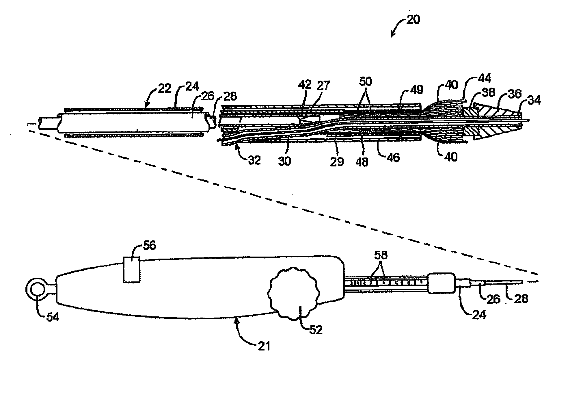
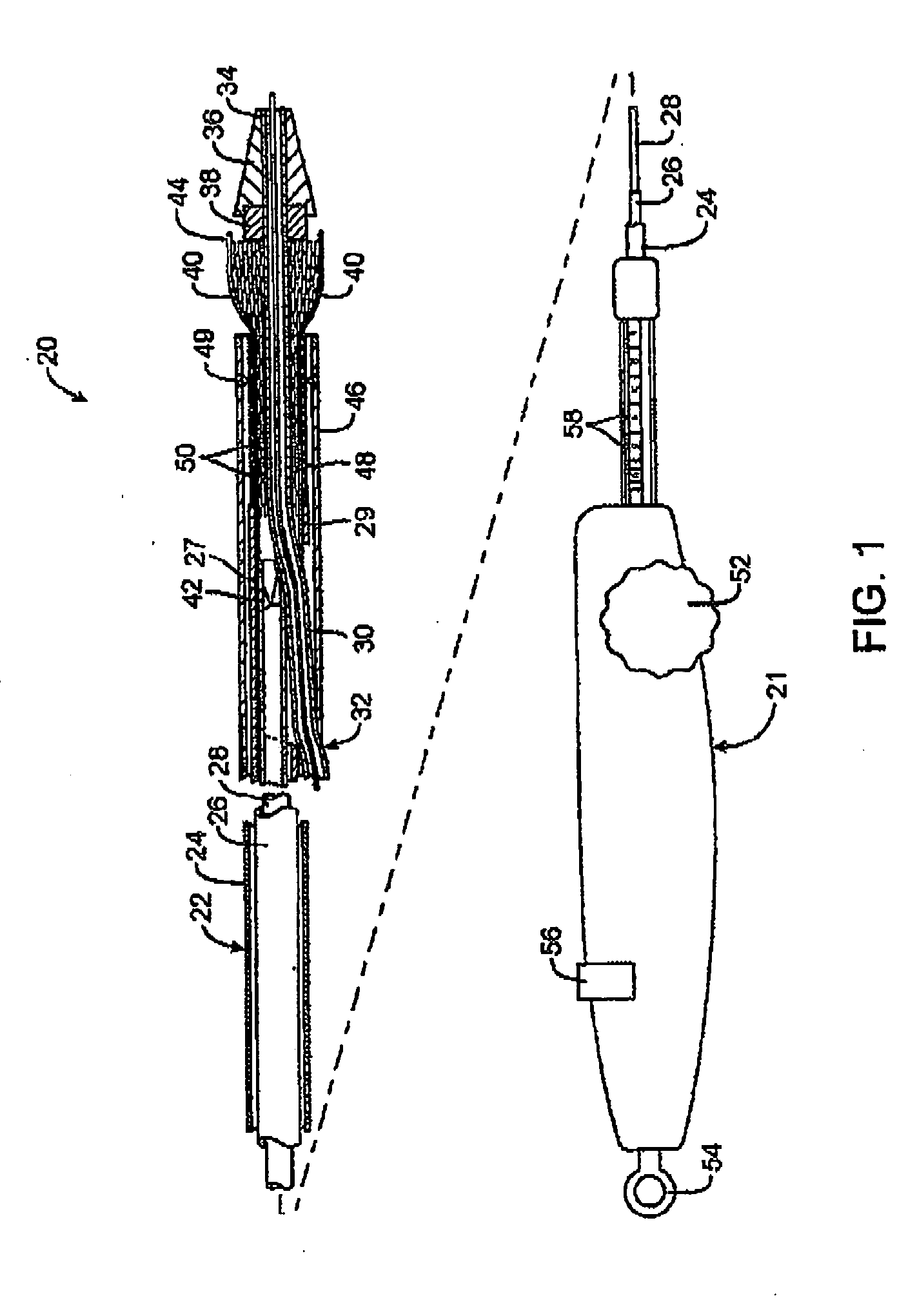
[0047] Referring to FIG. 1, a first embodiment of a prosthesis delivery catheter according to the invention is illustrated. Delivery catheter 20 may have any of various constructions, including that described in co-pending application Ser. No. 10 / 637,713, filed Aug. 8, 2003 (Attorney Docket No. 21629-000340), which is incorporated herein by reference. Delivery catheter 20 has a handle assembly 21 and an elongated catheter body 22 that includes three concentric tubular shafts all axially slidable relative to one another: an outer shaft 24, a pusher 26, and an inner shaft 28. Pusher 26 has a distal extension 27 to which a pusher ring 29 is fixed. In a distal region of the catheter body 22, a guidewire tube 30 extends slidably through a port 32 in outer shaft 24 and through pusher ring 29 and has a distal end 34, to which is mounted a nosecone 36 and a stop member 38.

[0048] Delivery catheter 20 further includes one or more stent expansion control members, which in the illustrated embo...


PUM


Abstract

Prosthesis delivery devices and methods are provided that enable precise control of prosthesis position during deployment. The prosthesis delivery devices may carry multiple prostheses and include deployment mechanisms for delivery of a selectable number of prostheses. Control mechanisms are provided in the prosthesis delivery devices that control either or both of the axial and rotational positions of the prostheses during deployment. This enables the deployment of multiple prostheses at a target site with precision and predictability, eliminating excessive spacing or overlap between prostheses. In particular embodiments, the prostheses of the invention are deployed in stenotic lesions in coronary or peripheral arteries, or in other vascular locations.

Description

CROSS REFERENCE TO RELATED APPLICATIONS [0001] The present application is a continuation-in-part of U.S. patent application Ser. No. 10 / 879,949 (Attorney Docket No. 021629-002700US), filed Jun. 28, 2004, the full disclosure of which is hereby incorporated by reference.BACKGROUND OF THE INVENTION [0002] Stents are tubular prostheses designed for implantation in a vessel to maintain patency of the vessel lumen. Stents are used in various vessels throughout the body, including the coronary arteries, femoral arteries, iliac arteries, renal artery, carotid artery, vascular grafts, biliary ducts, trachea, and urethra, to name some examples. Stents are typically implanted by means of long and flexible delivery catheters that carry the stents in a compact, collapsed shape to the treatment site and then deploy the stents into the vessel. In some applications, balloon expandable stents are used. These stents are made of a malleable metal such as stainless steel or cobalt chromium and are expa...

Claims


Application Information

Patent Timeline
IPC IPC(8): A61F2/82A61F2/84
CPCA61F2/95A61F2/958A61F2/966A61F2/97A61F2002/9665A61F2002/9505A61F2002/9511A61F2002/9583A61F2002/826
Inventor SNOW, DAVID W.KARRATT, JOSEPHGRAINGER, JEFFRY J.DEMARAIS, DENISE
Owner XTENT INC
Why Eureka
Try Eureka