Phase adjustment method and circuit for dll-based serial data link transceivers

a phase adjustment and serial data technology, applied in the field of delay locked loops, can solve problems such as pattern-dependent jitter, difficult to move the 0° clock transition relative to the data, and the sampling point is not optimized to be exactly in the center of the ey

Inactive Publication Date: 2006-01-05
AVAGO TECH WIRELESS IP SINGAPORE PTE
View PDF1 Cites 59 Cited by
  • Summary
  • Abstract
  • Description
  • Claims
  • Application Information

AI Technical Summary

Benefits of technology

[0013] The present invention is directed to a phase adjustment method and circuit for DLL-based serial dat...

Problems solved by technology

In high-speed data circuits, this is primarily due to the performance of the D flip flops, which is the limiting factor in the DLL performance.
This means that the sampling point is not optimized to be exactly in the center of the eye.
Conventionally, moving the 0° clock transitions relative to the data has been difficult.
This can result in pattern-dependent jitter.
Thus, even with today's modern process technology, the settling/hold time of DFF is still a li...

Method used


Image

  • Phase adjustment method and circuit for dll-based serial data link transceivers
  • Phase adjustment method and circuit for dll-based serial data link transceivers
  • Phase adjustment method and circuit for dll-based serial data link transceivers

Examples


Embodiment Construction

[0024] Reference will now be made in detail to the embodiments of the present invention, examples of which are illustrated in the accompanying drawings.

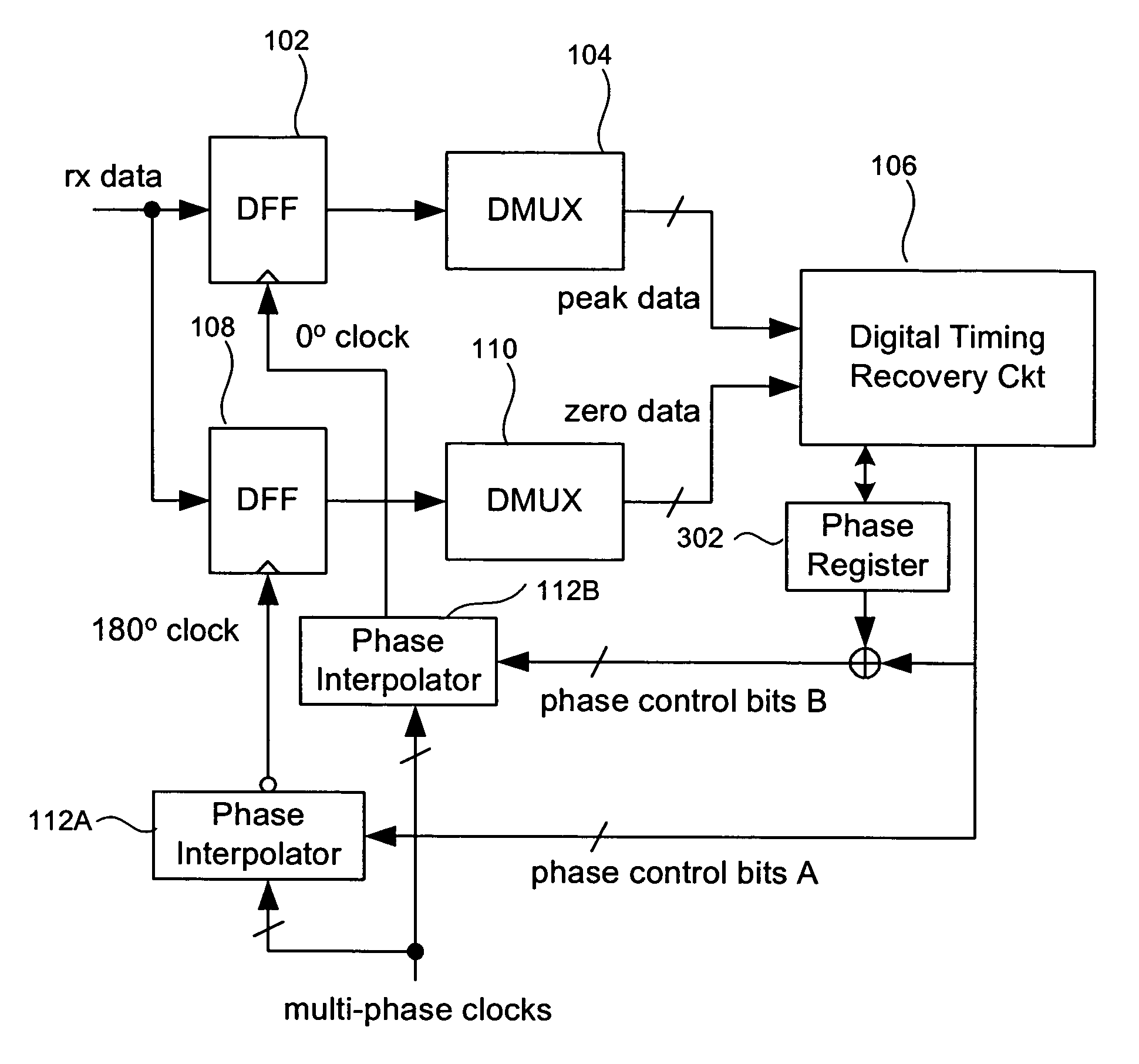
[0025] In the present invention, two separate phase interpolators are used to ensure that the 0° clock waveform has transitions that fall exactly in the center of the eye. The 0° clock and the 180° clock waveforms keep the same relationship relative to each other. Thus, the loop behavior does not change, but the sampling point moves back and forth, as required by the position by the center of the eye. When the input data has a high degree of jitter, the proposed approach will result in the optimal sampling point. In turn, this results in improved performance and lower bit error rate. Thus, with the circuit of FIG. 3, discussed below, the loop will lock in on the 180° clock, and will place the 0° clock close to, if not exactly at, the center of the eye. Additionally, it is possible to move the sampling point back and forth, in order ...


PUM


Abstract

A delay locked loop circuit with a first flip flop driven by a 0° clock and receiving the input data. A second flip flop by a 180° clock and receiving the input data. A first demultiplexer receives an output of the first flip flop and outputs peak data. A second demultiplexer receives an output of the second flip flop and outputs zero data. A timing recovery circuit outputs phase control bits based on the zero data and the peak data. A first phase interpolator outputs the 0° clock based on the phase control signal. A second phase interpolator outputs the 180° clock based on the phase control signal. A phase register receives the phase control signal from the timing recovery circuit. The first and second flip flops can be D flip flops. The first and second phase interpolators adjust relative phases of the 0° clock and 180° clock based on the phase control signal. The phase control signal can be a digital signal comprising a plurality of bits corresponding to a phase relationship between the 0° clock and 180° clock. The timing recovery circuit can be a digital circuit. The phase control signal is used to maintain a transition of the 0° clock near a center of an “eye” in the input data.

Description

BACKGROUND OF THE INVENTION [0001] 1. Field of the Invention [0002] The present invention is related to delay locked loops (DLLs), and more particularly, to reduction of jitter effects and improvement of link robustness in high-speed transceiver circuits using DLLs. [0003] 2. Related Art [0004] DLL (Delay Locked Loop)-based clock and data recovery is widely used in high speed data links. DLL-based clock and data recovery has two clocks. One clock typically comes from external incoming data, and a second clock comes from a local phase locked loop (PLL) with a local reference clock. The DLL extracts clock information from the incoming data and tries to lock the two clocks to each other, using delays. Since there is usually no way to change the local frequency of the PLL, which is locked to the local reference frequency, the variable that can be changed is the phase of the PLL output clock, or, equivalently, the delay. A phase detector used in DLL-based data clock recovery is called a ...

Claims


Application Information

Patent Timeline
IPC IPC(8): H04B17/00H03D1/00H04L27/06H04L7/00
CPCH03L7/0814H03L7/091H04L27/06H04L7/033H04L7/0337H04L7/0025
Inventor ZHANG, BO
Owner AVAGO TECH WIRELESS IP SINGAPORE PTE
Why Eureka
Try Eureka