Fluidics system

a fluidics and system technology, applied in the field of fluidics systems, can solve the problems of clogging of complex sample matrices by components of complex sample matrices, unsatisfactory demand for fluidics systems, and impracticality of portable analysis systems,

Inactive Publication Date: 2006-01-05
THE UNITED STATES OF AMERICA AS REPRESENTED BY THE SECRETARY OF THE NAVY
View PDF9 Cites 94 Cited by
  • Summary
  • Abstract
  • Description
  • Claims
  • Application Information

AI Technical Summary

Benefits of technology

[0008] The present invention also involves a portable analysis system forconduction of biochemical and/or chemical analysis that contains a three-dimensional fluid circuit; a first enclosed reservoir having a first adjustable vent; a second enclosed reservoir having a second adjustable vent; a first passageway for receiving a first fluid from the first reservoir; a second passageway for receiving a second fluid from the second reservoir; a primary fluid channel; a first connecting channel connecting the first passageway to the primary channel; a second connecting channel connecting the second passageway to the primary channel; a multimode waveguide; a barrier configured to prevent fluid flow between the first and second connecting channels; and a negative pressure source downstream of the primary fluid channel. The first and second reservoirs and passageways are elements of the fluid circuit. The fluid...

Problems solved by technology

Making these analysis systems portable presents unique demands on fluidics systems that have not been successfully met by currently available technology.
However, the size of these components makes them impractical for portable analysis systems.
While small valves of analogous design have been developed and are commercially available, as the valve size is reduced, clogs by the components of complex sample matrices become an important limitation.
However, micron-scale channels can become clogged when unprocessed environmental and clinical samples are used.
In addition, materials can be adsorbed onto channel walls and interfere with osmotic pumping.
Furthermore, these devices have a relatively low-volume throughput making them impractical for the analysis of milliliter volumes, as may be required for accurate measurement of trace constituents or analysis of inhomogeneous samples.
However, diaphragm-based valves can su...

Method used


Image

  • Fluidics system
  • Fluidics system
  • Fluidics system

Examples


example i

[0085] A schematic illustration of an exemplary fluid flow control arrangement 400 is depicted in FIG. 4. Arrangement 400 includes three reservoirs 416, 422, and 460 in which respective fluids 430, 432, 462 and gas space 434 are contained. The reservoirs are all fluid-tight (enclosed). Fluidly connected to each reservoir is a respective pressure relief valve 464, 466, 468. Pressure relief valves can be manually or remotely actuated to move between an open position where pressure relief or air is provided to the respective reservoir and a closed position where no pressure relief or air is provided to the respective reservoir. In this arrangement, pressure relief valves are each automatically actuated remotely by a suitable control 470 as schematically shown, and are in a closed (default) position when not actuated. Extending into or near a bottom of each respective reservoir is a respective outlet pathway or duct 418, 424, 472. The outlet ducts are connected by a manifold, 450, to a ...

example ii

[0088] Depicted schematically in FIG. 5 is a first embodiment of a portable bio / chemical analysis system 500 incorporating a fluid flow control arrangement as broadly discussed above whereby a plurality of sample fluids can be first simultaneously analyzed and then can be further simultaneously analyzed after addition of one or more reagents. The system includes a bio / chemical analysis device 574 having analyzing channels 576 in which analysis of a fluid can be performed as is well known in the art. One surface of the analyzing channels 576 can be a waveguide for performing optical analysis. For example, a waveguide in the plane of the figure co-extensive in area with the analysis device 574 could be used. Each analyzing channel 576 includes an associated inlet 578 and an associated outlet 580 as shown. Associated with each analyzing channel 576 is a sample reservoir / chamber 516 in which a sample fluid 530 and air 534 are respectively provided.

[0089] First pathways or ducts 518 res...

example iii

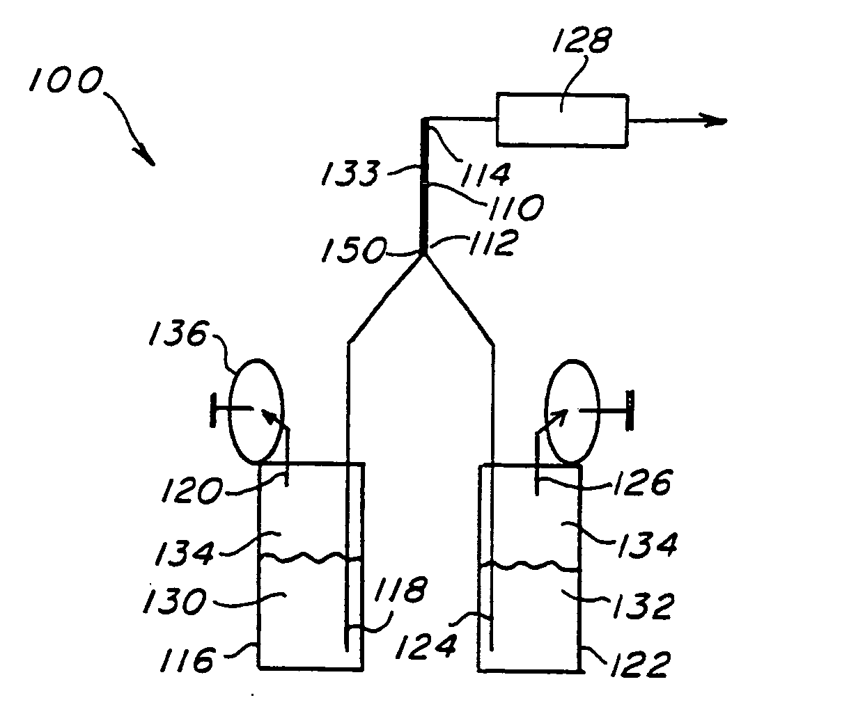
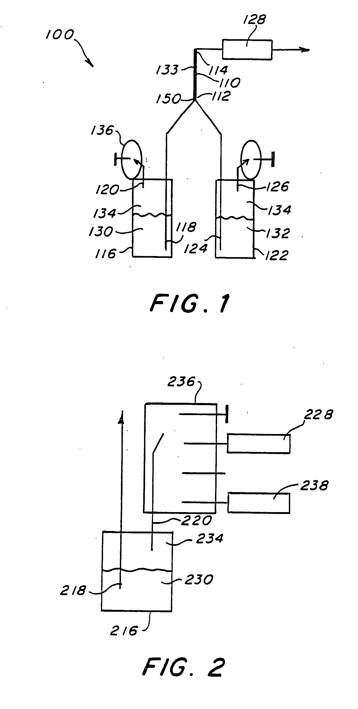
[0100] As shown schematically in FIG. 1, two reservoirs 116, 122 were connected through a manifold 150 to a primary fluid channel 110 comprising fluorescence detector, 133. The fluorescence detector was used to detect a fluorescent dye in one of the fluids 130, possibly water. The reservoir 116 contained water. Reservoir 122 contained a 60 nM aqueous solution of fluorescent dye Cy5, 132. Each reservoirwas sealed, closed, to the atmosphere except that each was connected to vents 120, 126 to micro relief valves 136 (“vent 1”) and (“vent 2”) (LFAA12034, The Lee Company), respectively. The default closed position of the valve caused the given reservoir to be sealed from the atmosphere. The relief valves 136 could be individually actuated (via a 12 volt signal) to open a given reservoir to atmospheric pressure. The negative pressure source 128 was a peristaltic pump, running at 1.5 ml / min. It was used to draw fluid from each of the reservoirs and through the fluid channel 110 comprising ...


PUM


Abstract

The present invention provides a fluidics system and a method for selectively drawing fluid from at least one selected reservoir into a channel by providing a negative pressure source downstream of the fluid and channel and selectively back filling the selected reservoir with a gas.

Description

[0001] This application claims the benefit of U.S. Provisional Application No. 60 / 231,548, filed on Sep. 11, 2000.FIELD OF THE INVENTION [0002] This invention relates to methods and systems of controlling fluid flow. This invention also relates to methods and systems of fluid flow control for sample analysis and methods, and systems of fluid flow control in portable fluidics systems. BACKGROUND [0003] Fluid control is necessary for many systems capable of automated chemical and biochemical analysis. These systems typically require liquid samples, reagents, and buffers to be dispensed in a controlled manner. Making these analysis systems portable presents unique demands on fluidics systems that have not been successfully met by currently available technology. These demands stem from the combined requirements of automation, compact size and compatibility with unprocessed samples, especially for field operations or point-of-care applications. For laboratory-scale devices, there is an a...

Claims


Application Information

Patent Timeline
IPC IPC(8): B01L3/02B01L3/00B01L99/00
CPCB01L3/502Y10T436/2575B01L3/50273B01L3/502738B01L2300/0654B01L2300/0816B01L2300/0864B01L2300/0867B01L2300/0887B01L2300/168B01L2400/049B01L2400/0622B01L2400/0633B01L2400/0655B01L2400/0694B01L2400/082B01L2400/084B01L3/5027Y10T137/0352
Inventor FELDSTEIN, MARK J.
Owner THE UNITED STATES OF AMERICA AS REPRESENTED BY THE SECRETARY OF THE NAVY
Why Eureka
Try Eureka