[0009] Accordingly, described herein is a catheter having a distal tip designed to decrease the outflow velocity of fluid being delivered by the catheter. In one variation, side holes are provided at the
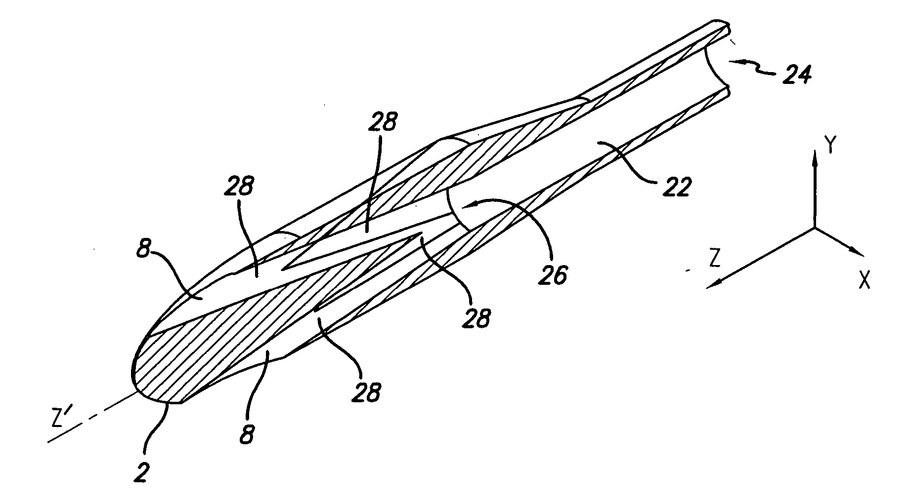
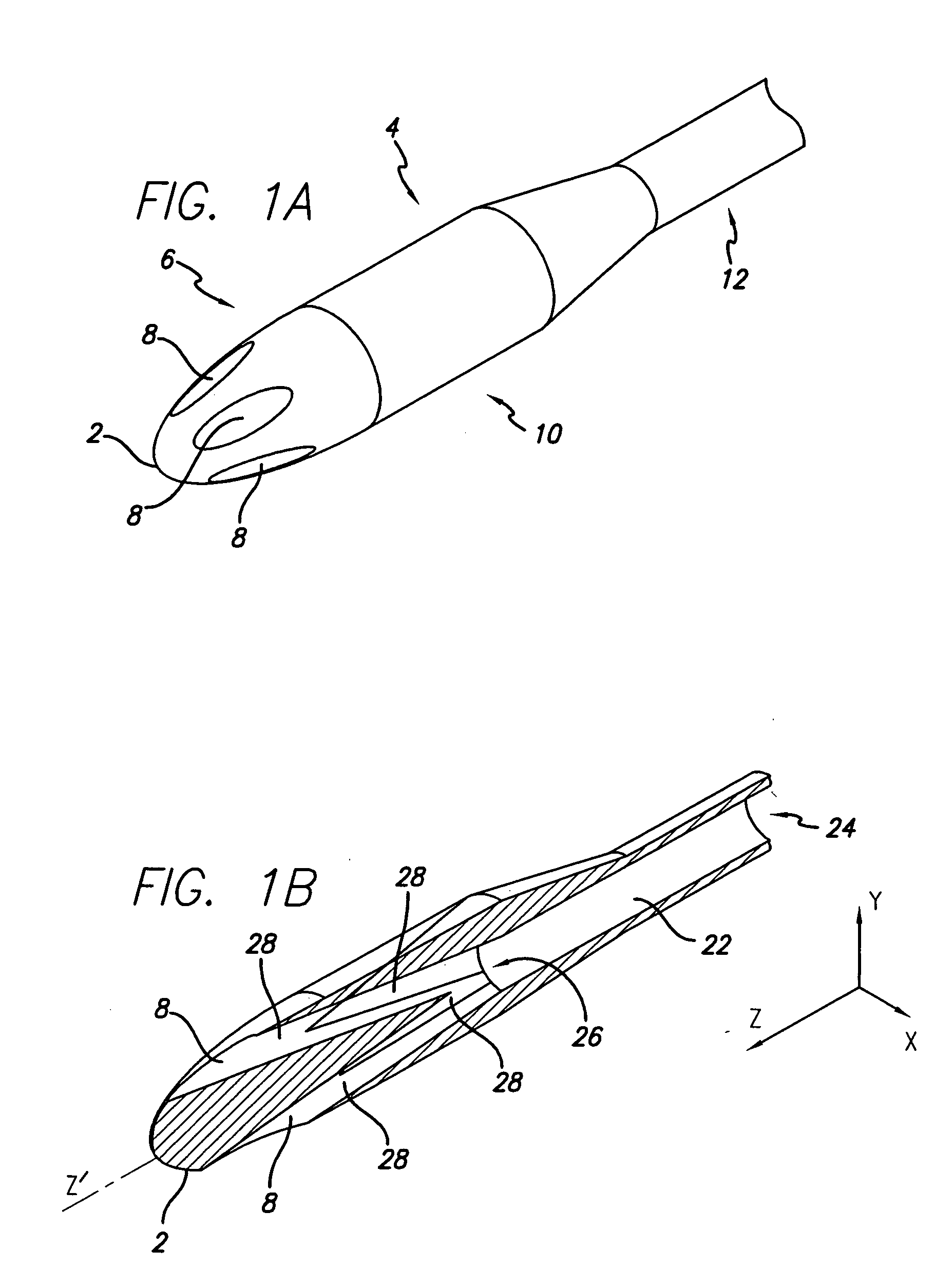
distal portion of the catheter to prevent jetting of fluids. In another variation, the distal portion of the catheter, where fluid exits the catheter, has an enlarged cross-sectional area relative to the cross-sectional area of a lumen in the proximal portion of the catheter. In yet another variation, the catheter has a bullet shaped
nose at the distal end of the catheter tip. Radially patterned openings may also be provided on the bullet shaped
nose to serve as outflow orifice.
[0010] The low outflow profile catheter tip may be implemented in a catheter having two or more lumens. For example, a low outflow profile catheter tip may be utilized in a
hemodialysis catheter. In one variation, the
hemodialysis catheter comprises two lumens where the orifice for each of the lumens at the distal portion of the catheter is staggered along the length of the catheter. The orifice at the distal end of the
hemodialysis catheter may be configured with a low outflow profile tip. The low outflow profile tip may decrease the outflow velocity of fluid being infused through the catheter such that the infusion of fluid causes minimal disruption on the existing circulatory flow within the patient's circulatory
system. For example, the distal end of the
hemodialysis catheter may be positioned in or close to the atrium of the patient's heart. A low outflow profile tip may be implemented to decrease the outflow velocity of blood being infused through the catheter such that the outflow of blood from the catheter does not cause significant disruption on the vortex flow that naturally occurs within the atrium of the heart. By minimizing the disruption on the vortex flow in the atrium, one may decrease the mixing of newly infused blood with the existing
venous blood (i.e., “dirty blood”), thus reducing the recirculation of the processed blood being infused by the catheter.
[0011] It has also been observed that a large flow velocity differential, between the velocity of the out flowing infused blood and the velocity of the natural
blood flow in the vessel, may promote the formation of
thrombosis at the distal tip of the catheter. By reducing the velocity of the blood flowing out of the catheter, the flow velocity differential between the natural and infused flow may be decreased, and this may decrease the
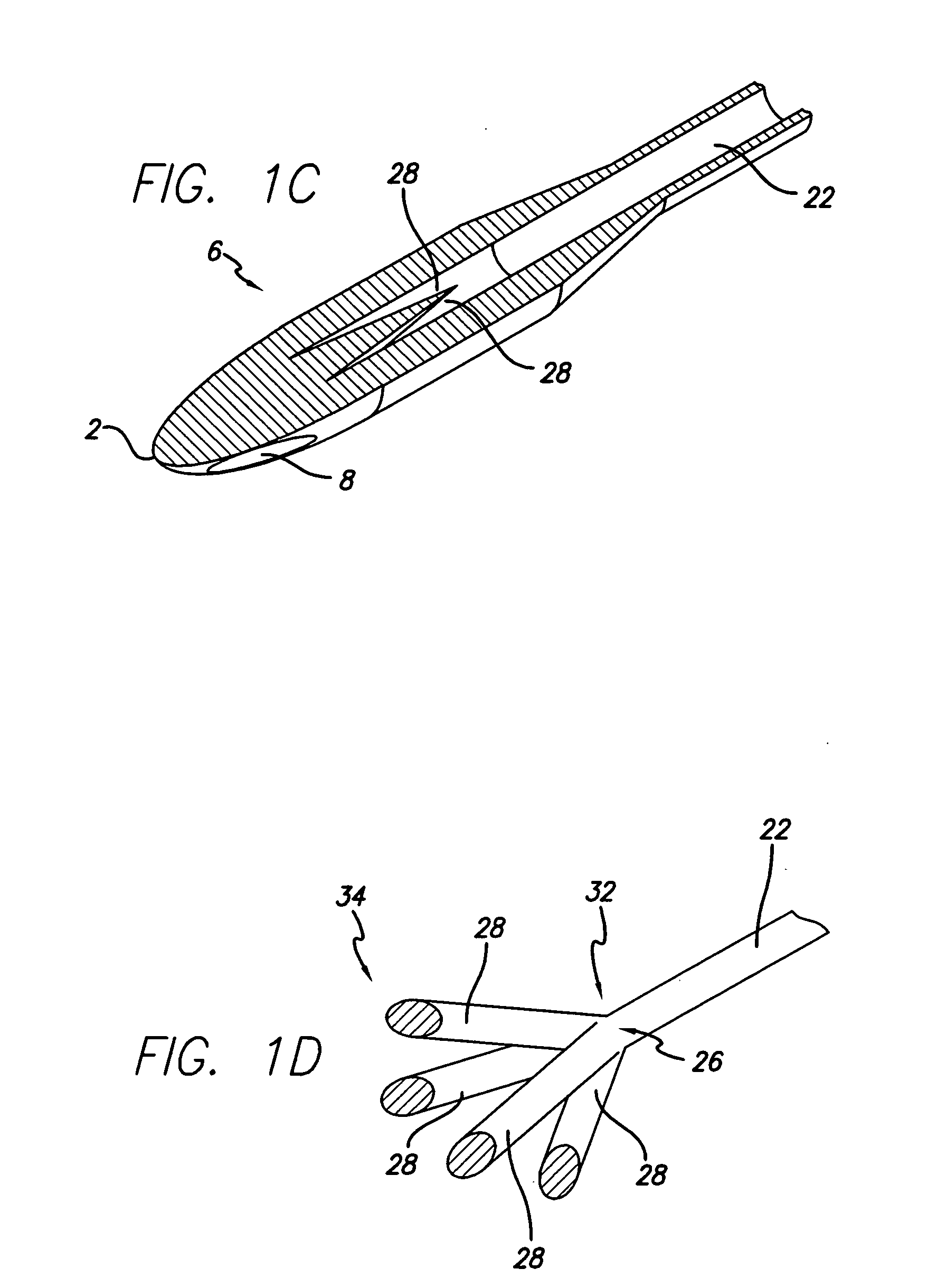
thrombus formation at the distal tip of the catheter. Furthermore, the shape of the catheter tip may be configured to create a uniform flow velocity across the entire cross-section directly distal to the catheter tip. Having multiple branching with increasing lumen cross-section within the catheter tip, the outflow of fluids may be dispersed into a larger cross-sectional flow and thus decrease the flow velocity. It may be desirable to control the dispersion such that a uniform flow velocity may be achieved directly distal to the catheter tip. Preferably, the dispersion is wide enough to provide sufficient reduction in overall flow velocity, but not too wide as to create a dead spot at the nose of the bullet shaped catheter tip.
[0012] In addition, the aspiration lumen opening of the dual lumen hemodialysis catheter may also be configured in a radial-pattern having a cross-sectional area equal or greater than the proximal portion of the aspiration lumen. This design may reduce the peak velocities of the
blood flow as it enters the catheter. One of ordinary skill in the art would appreciate that the “dirty blood” flowing down the major axis of the catheter must reverse direction as it enters the aspiration lumen of the catheter. This tends to cause
high shear stress around the fluid
entry point. In a traditional “staggered dual-D” design catheter, this
high stress at the fluid entry point may lead to the formation of
thrombosis. The
thrombus formation may result in the
occlusion of the lumen opening and reducing the effective life of the catheter. However, with a radial-pattern design and increased cross-sectional area at the aspiration lumen openings, one may reduced the peak velocities as the blood changes direction and enters the catheter. By decreasing the peak
inflow velocity, one may decrease the likelihood of thrombus formation at the fluid entry point. Furthermore, a design having greater cross-sectional areas and / or multiple openings for the aspiration lumen may accommodate the occasion when the catheter comes into contact with the vessel / atrium wall and one or several openings are blocked. One of ordinary skilled in the art, having the benefit of the disclosure herein, will appreciate that the number, shape (e.g., tapered shaped, etc.), and size (e.g., length of the opening, etc.) of the lumen openings can be configured to achieve the desired maximum flow velocity and / or
fluid shear stress.

