Scanning optical microscope

a scanning optical microscope and optical microscope technology, applied in the field of scanning optical microscopes, can solve the problems of difficult to realize positional control with high accuracy and high reproducibility, vibration of the objective adversely affecting the specimen under observation, and achieve the effects of reducing the degradation of off-axis performance, simple method, and simple arrangement or unnecessary

Inactive Publication Date: 2006-01-12
OLYMPUS CORP
View PDF8 Cites 26 Cited by
  • Summary
  • Abstract
  • Description
  • Claims
  • Application Information

AI Technical Summary

Benefits of technology

[0016] The present invention was made to solve the above-described problems associated with the prior art. Objects of the present invention are as follows. A first object of the present invention is to provide a scanning optical microscope, e.g. a laser scanning microscope (LSM), using a wavefront converting element, wherein even when the object pupil and the wavefront converting element are not placed in conjugate relation to each other, off-axis performance degradation is minimized, and wherein the wavefront converting element can be controlled by an extremely simple method, and a pupil relay optical system is simple in arrangement or unnecessary. A second object of the present invention is to provide an LSM using a wavefront converting element, in which the loss of light can be prevented even when the wavefront converting element is of the reflection type.

Problems solved by technology

With this method, however, it is difficult to realize positional control with high accuracy and high reproducibility because the method needs mechanical drive.
In a case where the specimen is moved, high-speed scanning cannot be effected when the specimen is large in size.
In observation of a biological specimen, if the objective is scanned in the state of being in direct contact with the specimen or immersed in a culture solution of the specimen, vibrations of the objective adversely affect the specimen under observation.
If the wavefront shape cannot properly be changed, image quality is likely to degrade considerably in an area where the object height is high.
This is extremely difficult.
This is, however, difficult to implement because of the following problems.
Therefore, when a plurality of objectives are switched from one to another to perform observation, it is difficult to keep the pupils of the objectives in conjugate relation to the wavefront converting element at all times.
Therefore, the apparatus becomes large in size and complicated unfavorably.
Further, even when a polarization beam splitter and a quarter-wave plate are used as stated above, it is not always possible to use a linearly polarized laser as a light source.

Method used


Image

  • Scanning optical microscope
  • Scanning optical microscope
  • Scanning optical microscope

Examples


Embodiment Construction

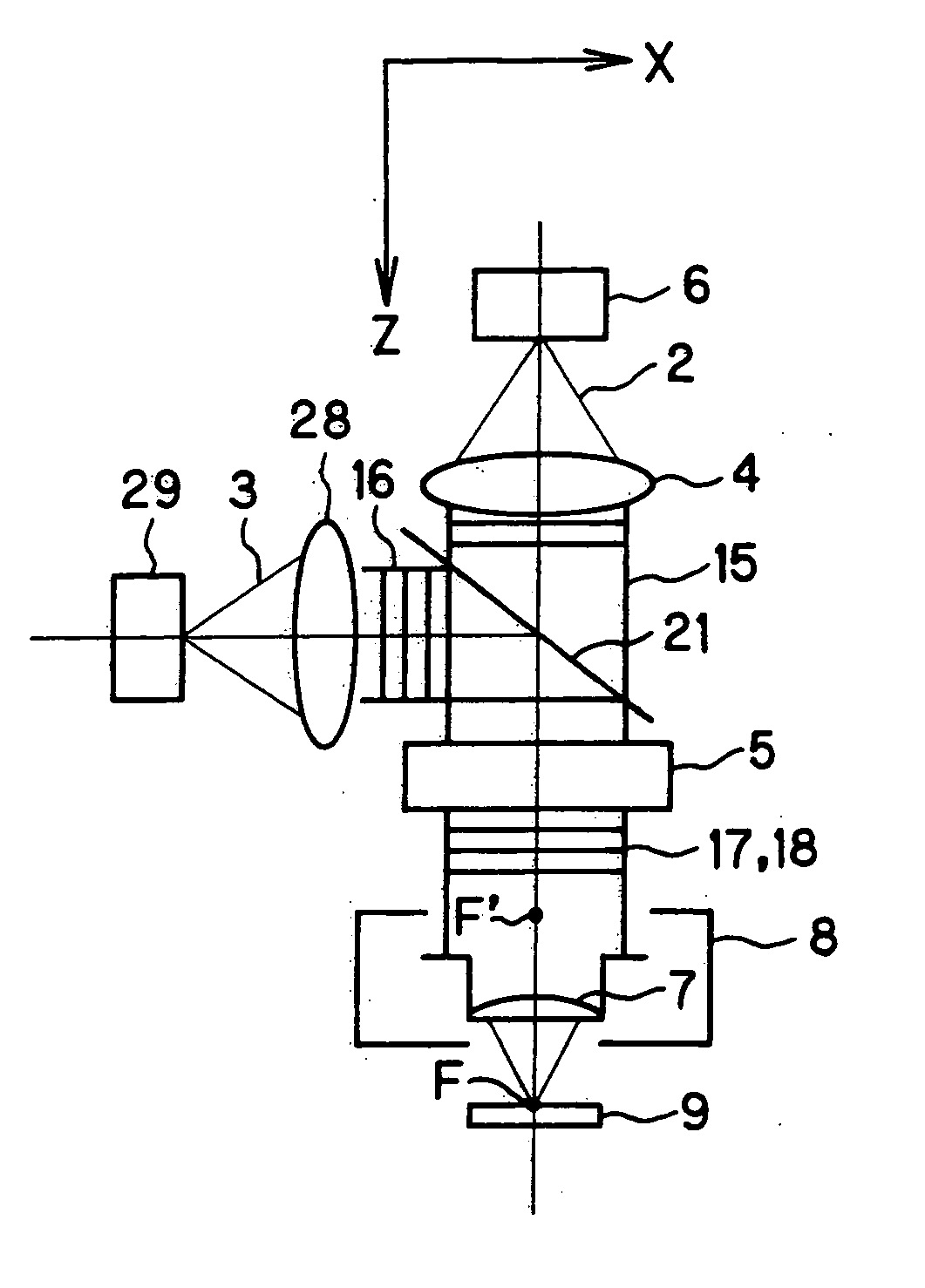
[0074] The arrangement and operation of the scanning optical microscopes according to the present invention will be described below specifically with reference to the accompanying drawings. It should be noted that the same elements repeatedly employed in the drawings, which are used for the following description, are denoted by the same reference numerals, and a redundant description thereof is not given. Further, the present invention will be described as a laser scanning microscope (LSM) using a laser oscillator as a light source.

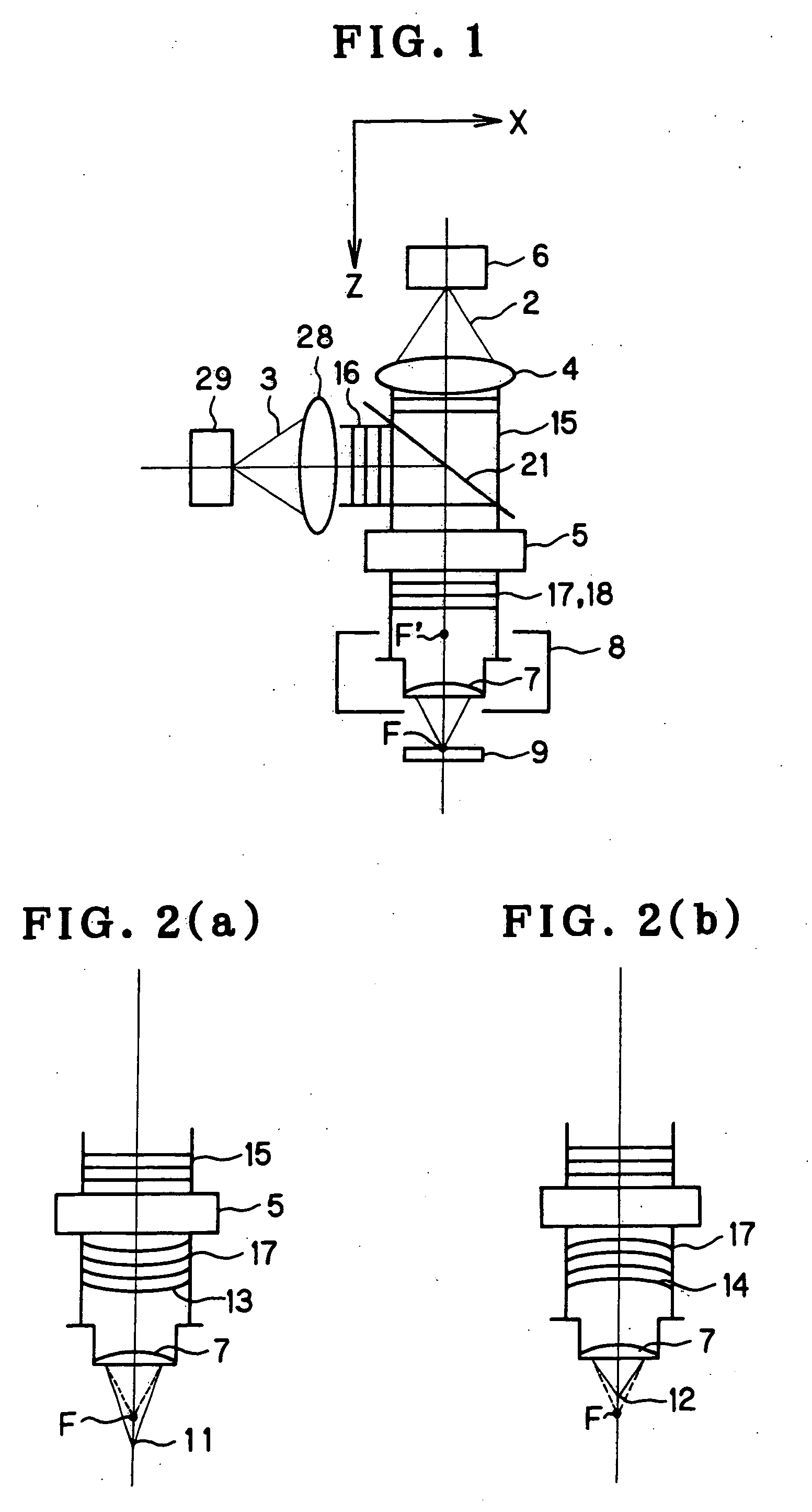
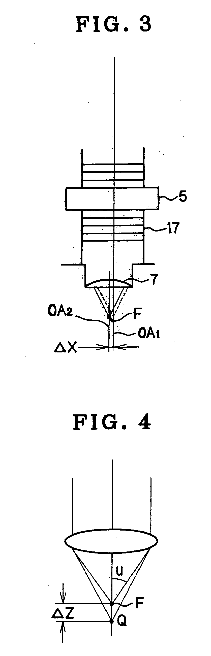
[0075] The basic arrangement of the first scanning optical microscope according to the present invention, together with wavefront aberration due to the movement of the object point during Z-scan (i.e. scan along the optical axis direction) and a variation of the arrangement, will be described below with reference to FIGS. 1 to 4.

[0076] An LSM can be realized by an arrangement as shown in FIG. 1. In FIG. 1, a laser light source 6 emits illuminating light...


PUM


Abstract

A scanning optical microscope using a wavefront converting element suffers minimum off-axis performance degradation and allows the wavefront converting element to be controlled by a simple method. Further, a pupil relay optical system is simple in arrangement or unnecessary. A laser scanning microscope includes a laser oscillator and a wavefront converting element for applying a desired wavefront conversion to a laserbeam emitted from the laser oscillator. An objective collects a wavefront-converted approximately parallel laser beam emerging from the wavefront converting element onto a sample. A detector detects signal light emitted from the sample. An actuator scans the objective along a direction perpendicular to the optical axis.

Description

[0001] This application claims benefit of Japanese Application No. 2000-394934 filed in Japan on Dec. 26, 2000, the contents of which are incorporated by this reference. BACKGROUND OF THE INVENTION [0002] 1. Field of the Invention [0003] The present invention relates to scanning optical microscopes and, more particularly, to a laser scanning microscope (LSM) that performs focal point movement along the direction of the optical axis by using a wavefront converting element. [0004] 2. Discussion of Related Art [0005] It has heretofore been necessary in order to obtain a three-dimensional image of a specimen with an LSM, for example, to capture optical images of successive planes inside the specimen by mechanically moving either the specimen or the objective along the direction of the optical axis. With this method, however, it is difficult to realize positional control with high accuracy and high reproducibility because the method needs mechanical drive. In a case where the specimen is...

Claims


Application Information

Patent Timeline
Patent Type & Authority Applications(United States)
IPC IPC(8): G02B21/00G02B21/06G02B27/00G02B27/09
CPCG02B21/0032G02B21/0036G02B21/0048G02B27/0068G02B21/006G02B21/0072G02B21/0076G02B21/0052
Inventor FUKUYAMA, HIROYAYOSHIDA, TAKEHIRO
Owner OLYMPUS CORP
Why Eureka
Try Eureka