Power supply apparatus capable of detecting abnormality of current flowing through drive circuit

a technology of power supply apparatus and drive circuit, which is applied in the direction of hybrid vehicles, lighting and heating apparatus, instruments, etc., can solve the problems of high accuracy, risk of electric shock, and electric motor seizing up or burning out, and achieve the effect of high accuracy

Active Publication Date: 2006-01-12
DENSO CORP
View PDF14 Cites 25 Cited by
  • Summary
  • Abstract
  • Description
  • Claims
  • Application Information

AI Technical Summary

Benefits of technology

[0019] An object of the present invention is to provide a power supply apparatus capable of dete

Problems solved by technology

When a DC power supply of such a high voltage is used, however, the electric motor may seize up or burn out due to overheat at the time of overload.
There may also be a risk of receiving an electric shock at the time of electric leakage.
This poses a problem in accuracy of abnormality detection in the following points.
When a large current exceeding the rated current flows through the inverter, the inverter will suffer temporarily a great load in accordance with the magnitude of the passing current and the time period during which it flows, possibly leading to breaking of the inverter.
Meanwhile, when the current continuously flows in the vicinity of the upper limit of sine wave, the inverter will continuously suffer the load of the maximum level in the normal operation, which may also break the inverter.
Thus, in the above-described abnormality detection method, the abnormal current temporarily exceeding the rated current considerably is determined to be abnormal if the time period during which it flows exceeds a prescribe

Method used


Image

  • Power supply apparatus capable of detecting abnormality of current flowing through drive circuit
  • Power supply apparatus capable of detecting abnormality of current flowing through drive circuit
  • Power supply apparatus capable of detecting abnormality of current flowing through drive circuit

Examples


first embodiment

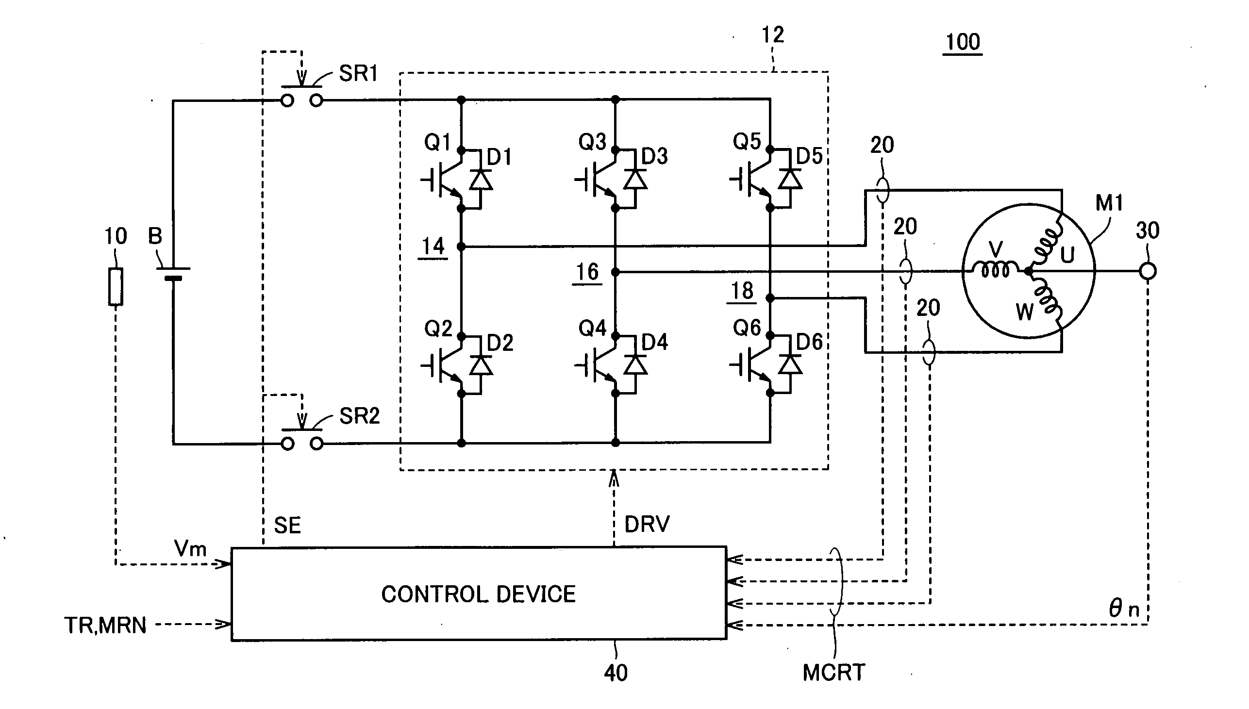
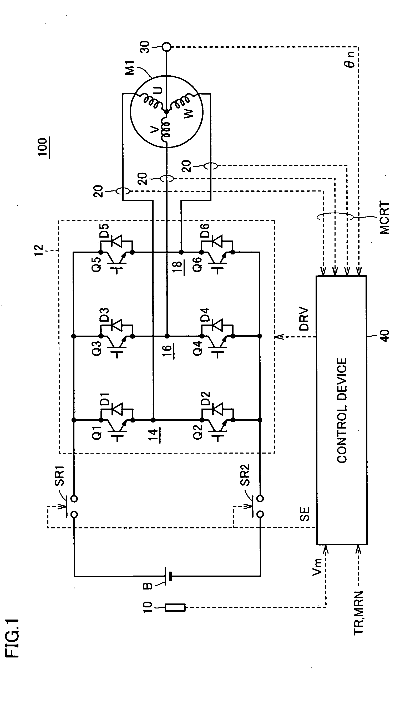
[0057]FIG. 1 schematically shows a power supply apparatus according to a first embodiment of the present invention.

[0058] Referring to FIG. 1, the power supply apparatus 100 includes a DC power supply B, a voltage sensor 10, system relays SR1 and SR2, an inverter 12, a current sensor 20, a resolver 30, and a control device 40.

[0059] An AC motor M1 is a drive motor that generates torque for driving drive wheels of a hybrid or electric vehicle. It is a motor that can function as an electric power generator driven by the engine and also function as an electric motor for the engine to start the engine for example.

[0060] Inverter 12 is constituted of a U-phase arm 14, a V-phase arm 16, and a W-phase arm 18, which are arranged in parallel between a power supply line and a ground line.

[0061] U-phase arm 14 is formed of NPN transistors Q1, Q2 connected in series, V-phase arm 16 is formed of NPN transistors Q3, Q4 connected in series, and W-phase arm 18 is formed of NPN transistors Q5, Q...

second embodiment

[0120]FIG. 7 is a block diagram of an abnormal current detection circuit in a power supply apparatus according to a second embodiment of the present invention. The power supply apparatus of the present embodiment is identical to power supply apparatus 100 of FIG. 1 except that abnormal current detection circuit 402a is replaced with an abnormal current detection circuit 402b, and thus, detailed description of the common portions will not be repeated.

[0121] Referring to FIG. 7, abnormal current detection circuit 402b includes a current detection unit 60b, an abnormality determination unit 62b, a relay drive unit 64, a notification unit 66, and a control mode determination unit 68.

[0122] Current detection unit 60b, as in the first embodiment, starts sampling of motor current MCRT in the first operation cycle corresponding to the shortest operation cycle of the CPU when motor current MCRT exceeds threshold value MCRT_std. Current detection unit 60b captures and holds maximum motor cu...

third embodiment

[0151]FIG. 10 is a block diagram of an abnormal current detection circuit in a power supply apparatus according to a third embodiment of the present invention. The power supply apparatus of the present embodiment is identical to power supply apparatus 100 shown in FIG. 1 except that abnormal current detection circuit 402a is replaced with an abnormal current detection circuit 402c, and thus, detailed description of the common portions will not be repeated.

[0152] Referring to FIG. 10, abnormal current detection circuit 402c includes a current detection unit 60c, an abnormality determination unit 62c, a relay drive unit 64, and a notification unit 66.

[0153] Current detection unit 60c, similarly to current detection unit 60a of the first embodiment, starts sampling of motor current MCRT in the first operation cycle corresponding to the shortest operation cycle of the CPU when motor current MCRT exceeds threshold value MCRT_std. Further, current detection unit 60c captures and holds m...


PUM


Abstract

A current detection unit starts sampling of a motor current at the timing when the motor current has exceeded a threshold value, and holds a maximum motor current value for each prescribed operation cycle. An abnormality determination unit determines whether the maximum motor current value is greater than the threshold value, and counts the number of times that the maximum motor current value continuously exceeds the threshold value. When the count value has reached at least 3, the abnormality determination unit generates and outputs a detection signal indicating abnormality in the motor current to a relay drive unit and a notification unit. The relay drive unit in receipt of the detection signal generates a signal to turn off the system relays. The notification unit generates and outputs a signal AL to display means outside the power supply apparatus.

Description

[0001] This nonprovisional application is based on Japanese Patent Applications Nos. 2004-200714 and 2005-079831 filed with the Japan Patent Office on Jul. 7, 2004 and Mar. 18, 2005, respectively, the entire contents of which are hereby incorporated by reference. BACKGROUND OF THE INVENTION [0002] 1. Field of the Invention [0003] The present invention relates to a power supply apparatus, and more particularly to a power supply apparatus having a function to detect abnormality of a current flowing through a drive circuit incorporated in the power supply apparatus. [0004] 2. Description of the Background Art [0005] Hybrid vehicles and electric vehicles have been attracting attention as they help the environment. The hybrid vehicle includes, as its power source, a direct current (DC) power supply, an inverter and a motor driven by the inverter, in addition to a conventional engine. Specifically, the engine is driven to generate power while a DC voltage from the DC power supply is conve...

Claims


Application Information

Patent Timeline
IPC IPC(8): H02H3/00G01R19/165H02M7/48H02P27/06
CPCB60L3/0023B60W20/00B60W10/08B60W20/50B60W10/30
Inventor OCHIAI, KIYOEYAGUCHI, HIDEAKIUECHI, TATSUYUKIYAGI, KOJI
Owner DENSO CORP
Why Eureka
Try Eureka