Hole-trapping materials for improved OLED efficiency
a technology of oled efficiency and hole trapping, which is applied in the direction of discharge tube luminescnet screens, natural mineral layered products, etc., can solve the problems of insufficient el efficiency, insufficient luminous efficiency, and limiting the competitiveness of oled applications, so as to improve the luminance yield and improve the color coordinates
- Summary
- Abstract
- Description
- Claims
- Application Information
AI Technical Summary
Benefits of technology
Problems solved by technology
Method used
Image
Examples
##ventive examples 1-5
COMPARATIVE AND INVENTIVE EXAMPLES 1-5
Efficiency-Improving Effect of the Hole-Trapping Material on Electroluminescence of Blue OLEDs
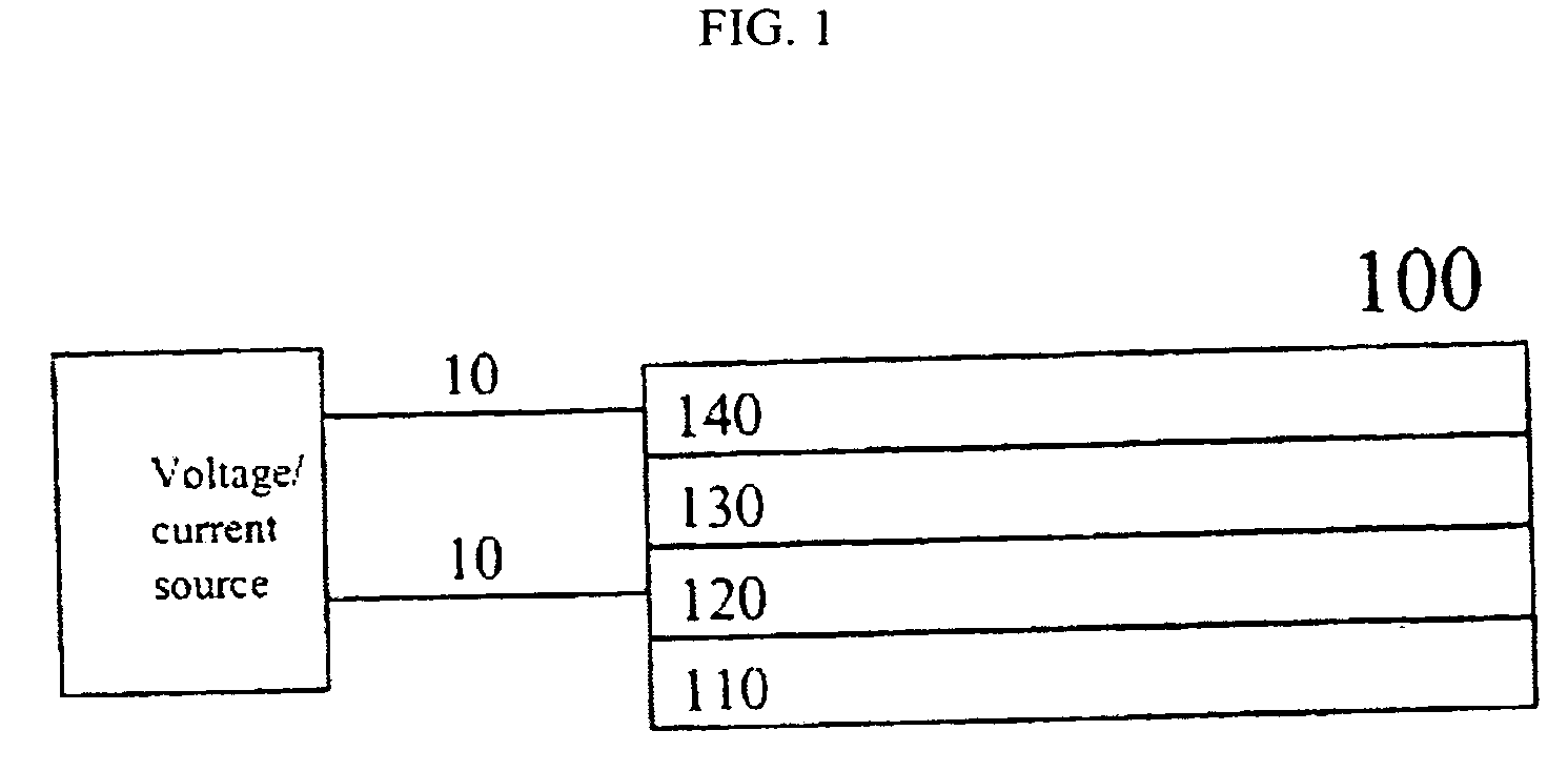
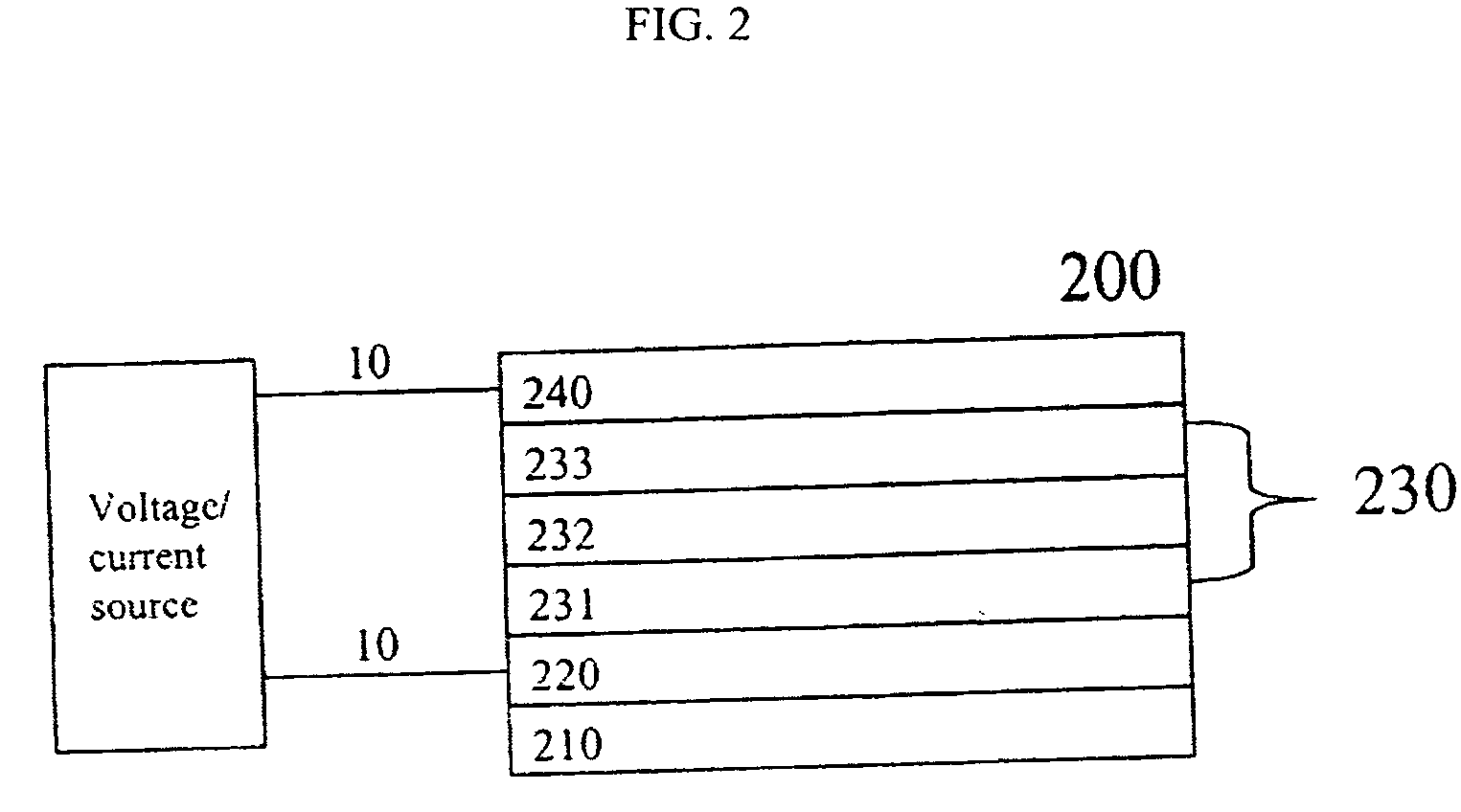
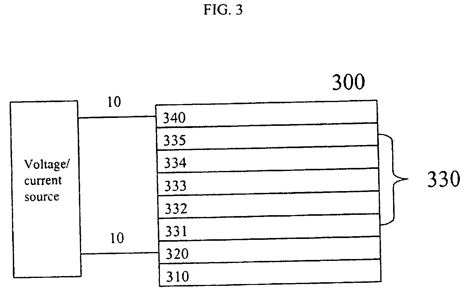
[0359] OLED devices were prepared as follows. A glass substrate coated with about 850 Å transparent indium-tin-oxide (ITO) conductive layer was cleaned and dried using a commercial glass scrubber tool. The ITO surface was subsequently treated with an oxidative plasma to condition the surface as an anode. Over the ITO was deposited a 10 Å thick hole-injecting layer of fluorocarbon (CFx) by plasma-assisted deposition of CHF3. The following layers were deposited in the following sequence by sublimation from heated crucible boats in a conventional vacuum deposition chamber under a vacuum of approximately 10−6 Torr: (1) a hole-transport layer, 750 Å thick, including NPB; (2) a light-emitting layer, 400 Å thick, including host and dopant and the hole-trapping material in certain ratio (indicated in Tables 1-3); (3) an 200 Å electron-transport layer, includin...
##ventive examples 6-8
COMPARATIVE AND INVENTIVE EXAMPLES 6-8
Efficiency-Improving Effect of the Hole-Trapping Material on Electroluminescence of Blue OLEDs Containing Lithium Dopant in the Electron-Transporting Layer
[0363] For layer thicknesses and concentrations of materials in multi-component layers of each device see Table 2. OLED devices were prepared similar to Examples 1-5 except the electron-transporting layer AlQ3 was doped with alkali metal, lithium, in the 1:1 molar ratio.
[0364] The EL characteristics of these devices are given in Table 2.
[0365] As can be seen from Table 2, Inventive Examples 6-8 demonstrate addition of the hole-trapping material at concentration of less than 5% results in the electroluminescence efficiency improvement of greater than 2 times than that of comparative devices for devices containing a variety of hosts with the dopant Blue 2 and lithium doping of the electron-transporting layer.
TABLE 2Comparative and inventive examples:Efficiency,W / A at 20λmaxW / A vs J@20 mA / cm...
##ventive examples 9 and 10
COMPARATIVE AND INVENTIVE EXAMPLES 9 AND 10
Efficiency-Improving Effect of the Hole-Trapping Material on Electroluminescence of Blue-Green OLEDs Containing Blue-Green 2 Dopant
[0366] For layer thicknesses and concentrations of materials in multi-component layers of each device see Table 3. OLED devices were prepared similar to Examples 1-5 except that in place of the blue dopants the light-emitting layer contained 1-5% dopant Blue-Green 2.
[0367] The EL characteristics of these devices are given in Table 3.
[0368] As can be seen from Table 3, Inventive Examples 9 and 10 demonstrate addition of the hole-trapping material at concentration of less than 5% results in the device luminance efficiencies improvement to 0.10-0.11 W / A. Moreover, a thicker light-emitting layer comprising hole-trapping material, host, and dopant followed by an electron-transporting layer with added alkali metal dopant can provide 0.134 W / A (12.4 cd / A) at color coordinates of 0.16, 0.39 and a lifetime of 1,200 h ...
PUM
| Property | Measurement | Unit |
|---|---|---|
| Fraction | aaaaa | aaaaa |
| Fraction | aaaaa | aaaaa |
| Percent by volume | aaaaa | aaaaa |
Abstract
Description
Claims
Application Information
 - R&D
- Intellectual Property
- Life Sciences
- Materials
- Tech Scout
- Unparalleled Data Quality
- Higher Quality Content
- 60% Fewer Hallucinations
Browse by: Latest US Patents, China's latest patents, Technical Efficacy Thesaurus, Application Domain, Technology Topic, Popular Technical Reports.
© 2025 PatSnap. All rights reserved.Legal|Privacy policy|Modern Slavery Act Transparency Statement|Sitemap|About US| Contact US: help@patsnap.com


