Electrochemical device comprising electrode lead having protection device

a protection device and electrode lead technology, applied in the direction of primary cell maintenance/servicing, batteries, cell components, etc., can solve the problems of battery explosion, low capacity of lithium polymer batteries developed up to date, complex manufacturing processes, etc., and achieve the effect of minimizing the drop in energy density per volum

Active Publication Date: 2006-01-12
LG ENERGY SOLUTION LTD
View PDF6 Cites 44 Cited by
  • Summary
  • Abstract
  • Description
  • Claims
  • Application Information

AI Technical Summary

Benefits of technology

[0012] Therefore, the present invention has been made in view of the above-mentioned problems. It is an object of the present invention to provide an electrochemical device, which comprises a protection device activated immediately in response to an increase in temperature of the electrochemical device to interrupt electric current so that the electrochemical device can be protected while minimizing a drop in energy density per volume of electrochemical device.
[0019] The PTC device used in the present invention as protection device, which is electrically connected to an electrode lead in series, can interrupt electric current by the occurrence of a rapid increase in resistance, when the temperature of a battery increases abnormally (for example, in the case of an over-current or external short circuit, particularly in the case of an overcharge), so that the temperature cannot increase any more. Therefore, the PTC device can improve the battery safety.
[0020] In one embodiment of the present invention, the protection device is disposed inside of the casing of electrochemical device, and the largest surface of the protection device is layered on the lateral surface in the casing where the electrode lead is present. For example, in the case of a stacked electrode assembly having four stacked surfaces, the protection device is disposed in the space between the stacked surface on which the electrode lead is present and the casing, and the surface of the protection device is opposite to the stacked surface on which the lead is present. In this case, the protection device can respond promptly to an increase in temperature of the electrochemical device with no occurrence of a drop in energy density of the electrochemical device.
[0024] In another embodiment, the protection device is disposed at the sealing region between inner surfaces of a casing. In this case, it is preferable to minimize the temperature and pressure upon sealing so that the breakage of the protection device itself can be prevented.
[0025] Meanwhile, it is more efficient in terms of safety that the protection device has a contact surface with the electrode assembly as large as possible so that the heat generated from the inside of the electrode assembly can be detected with high sensitivity. Therefore, it is preferable that the protection device extends by a predetermined length along the direction away from the longitudinal direction of the lead connected by the protection device, preferably along the perpendicular direction (see, FIGS. 2c, 2d, 2e and 2f). By doing so, the protection device can extend on the lateral surface of the casing, while minimizing a drop in energy density per volume caused by such extended protection sheet. If the protection device is disposed at the sealing region of the casing and the sealing region of the casing is folded to be layered on the lateral surface of the casing, the extended portion of the protection device is also layered on the lateral surface of the casing. Particularly, when the protection device is present in the vicinity of an electrode tab lead, the heat generated from an electrochemical device during an overcharge state is conducted mainly through the electrode lead. As a result, heat conductivity to the protection device may decrease. Therefore, according to the present invention, the portion of the protection device exposed by extending from a linear lead, preferably along the perpendicular direction, can improve the sensitivity to an increase in temperature of the electrochemical device as well as heat conductivity (see, FIGS. 3, 7 and 11). In other words, the heat generated from the electrochemical device under an overcharge state can be conducted not only through the electrode lead but also directly to the exposed portion of the protection device, thereby increasing operational efficiency of the protection device.
[0027] When the protection device is disposed in the space between a cathode tab and anode tab in a stacked electrode assembly including an electrode tab having a V-form (see, FIG. 7a) as described above, there is no drop in capacity of the battery. Additionally, it is possible to maximize the contact area between the protection device and the battery.

Problems solved by technology

However, such lithium secondary batteries have disadvantages in that organic electrolytes used therein may cause safety-related problems resulting in ignition and explosion of the batteries and that processes for manufacturing such batteries are complicated.
However, such lithium polymer batteries developed up to date have a relatively low capacity compared to lithium ion batteries and provide insufficient discharge capacity at low temperature.
To satisfy this, safety of batteries is strictly restricted in terms of ignition and combustion in batteries by safety standards.
Overcharge of a battery is the most imminent problem to be solved.
All batteries are dangerous when overcharged and lithium ion batteries cannot be an exception.
Such dendrite may result in explosion and firing of a battery when the battery is abused.
The most dangerous phenomenon resulting from overcharge of a battery is “high-temperature overcharge”, which is the worst case occurring in lithium ion batteries.
However, there is no occurrence of ignition in the closed spaced of a battery because oxygen is not supplied thereto.
The latter structure is not stable.
Therefore, in this case, remaining oxygen moves to an electrolyte so that oxygen may be supplied to the electrolyte reaching its flash point, thereby causing explosion of a battery.
However, because a battery itself cannot prevent the heat emission as mentioned above, many attempts have been made, for example, to mount a protection circuit on a battery or to apply heat obstruction by using a separator.
However, according to the battery, because the PTC device is mounted on the exterior of a battery and the battery casing has low heat conductivity, it is not possible to respond sensitively to variations in temperature inside of the battery in practice.
Further, because the battery is manufactured through a complicated process, it shows poor industrial applicability in practice.

Method used


Image

  • Electrochemical device comprising electrode lead having protection device
  • Electrochemical device comprising electrode lead having protection device
  • Electrochemical device comprising electrode lead having protection device

Examples


example 1

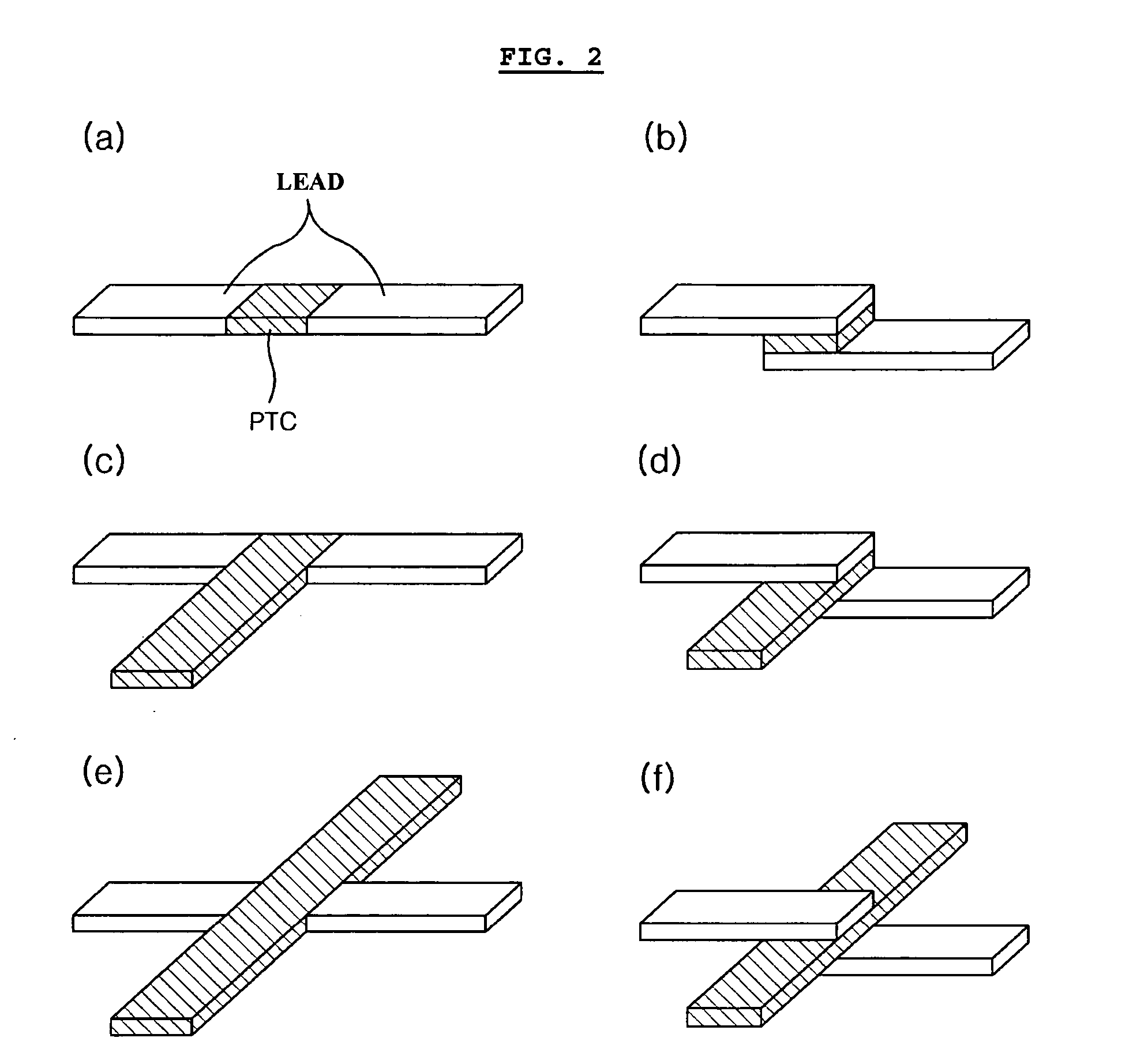
[0061] The same lithium ion polymer secondary battery available from LG Chem., Ltd. and the same PTC device available from LG Cable Co. as Comparative Example 1 were used. In this Example, the PTC device was heat sealed with a cathode lead to provide the form as shown in FIG. 2b. Then, the battery was enclosed with a pouch-type casing in such a manner that the PTC portion is present at the inner sealing region of the casing as shown in FIG. 5.

example 2

[0062] The same lithium ion polymer secondary battery available from LG Chem., Ltd. and the same PTC device available from LG Cable Co. as Comparative Example 1 were used. Similarly, the PTC device was heat sealed with a cathode lead to provide the form as shown in FIG. 2b. Then, the battery was enclosed with a pouch-type casing in such a manner that the PTC portion is present inside of the casing as shown in FIG. 6a. Particularly, in order to minimize the loss of energy density, the lead was folded so that the PTC sheet is disposed between the stacked surface (surface having the lead) of the electrode assembly and the casing. Additionally, the lead was insulated by using an imide film so as to prevent interconnection between leads (see, FIG. 6a).

example 3

[0063] The same lithium ion polymer secondary battery available from LG Chem., Ltd. and the same PTC device available from LG Cable Co. as Comparative Example. 1 were used. Similarly, the PTC device was heat sealed with a cathode lead to provide the form as shown in FIG. 2d. Then, the battery was enclosed with a pouch-type casing in such a manner that the extended portion of the PTC sheet is present between the cathode tab and anode tab. Additionally, the PTC sheet was coated with a polymer so as to prevent breakage of the PTC layer caused by infiltration of electrolyte.


PUM

PropertyMeasurementUnit
voltageaaaaaaaaaa
temperatureaaaaaaaaaa

Abstract

Disclosed is an electrochemical device including an electrode assembly having a cathode, anode and an electrolyte, and a casing surrounding the electrode assembly. The device further includes a protection device to which either or both of a cathode lead for connecting a cathode with an outer terminal and an anode lead for connecting an anode with an outer terminal are connected electrically, wherein the protection device is disposed in the inner space of the casing and the electrode lead equipped with the protection device is folded at both sides of the protection device so that the largest surface of the protection device is layered on a lateral surface of the casing where the electrode lead is present.

Description

TECHNICAL FIELD [0001] The present invention relates to an electrochemical device comprising an electrode lead having a protection device for interrupting electric current when the temperature of an electrochemical device increases. BACKGROUND ART [0002] Recently, there is an increasing interest in energy storage technology. Batteries have been widely used as energy sources in portable phones, camcorders, notebook computers, PCs and electric cars, resulting in intensive research and development into them. In this regard, electrochemical devices are subjects of great interest. Particularly, development of rechargeable secondary batteries is the focus of attention. Recently, research and development into novel electrode and battery that can improve capacity density and specific energy have been made intensively in the field of secondary batteries. [0003] Among currently used secondary batteries, lithium secondary batteries appearing in early 1990's have drive voltage and energy densit...

Claims


Application Information

Patent Timeline
Patent Type & Authority Applications(United States)
IPC IPC(8): H01M10/00H01M10/50H01M6/50H01M10/05H01M50/119H01M50/136H01M50/178H01M50/574H01M50/583H01M50/588H01M50/595
CPCH01M2/0267H01M2/0275H01M2/06H01M2/34H01M2/348H01M10/0525Y02T10/7011H01M10/5026H01M10/5032H01M2200/10H01M2200/101H01M2200/103H01M2200/106H01M10/5004H01M10/637H01M10/647H01M10/613Y02E60/10H01M50/581H01M50/588H01M50/595H01M50/583H01M50/119H01M50/178H01M50/574H01M50/136H01M50/572H01M50/20H01M50/543
Inventor KIM, JE YOUNGAHN, SOON HOPARK, PIL KYUCHOI, SOO ANLEE, YONG TAEKIM, JU DAM
Owner LG ENERGY SOLUTION LTD
Why Eureka
Try Eureka