Power tong with linear camming surfaces

a technology of power tongs and camming surfaces, which is applied in the direction of wrenches, spanners, drilling accessories, etc., can solve the problems of reducing the gripping force applied to the tubular, wear to the components, and certain amount of “play” in the mechanism, so as to increase the distance, increase the force, and the radial distance to a point

Inactive Publication Date: 2006-01-19
KATHAN MURRAY
View PDF10 Cites 25 Cited by
  • Summary
  • Abstract
  • Description
  • Claims
  • Application Information

AI Technical Summary

Benefits of technology

[0007] The present invention addresses this need by providing a pivoting-jaw power tong in which the primary camming surfaces of rotary gear have a novel geometry. Each primary camming surface has a substantially linear configuration, rather than a circularly-curved configuration. More specifically, each primary camming surface is oriented so as to form an acute angle with a radial line extending from the rotary gear to the point where the primary camming surface meets its corresponding neutral recess. By virtue of this geometric configuration, the radial distance to a point on any of the primary camming surfaces reduces, in substantially linear fashion, with increased distance away from the neutral recess. Therefore, increased rotation of the ring gear in either direction away from the neutral position will cause both jaws to rotate further inward, thus increasing the force that the dies on the free ends of the jaws will exert on a tubular being engaged by the apparatus.
[0008] The inventor has discovered that when using a power tong having such linearly-configured primary camming surfaces, the dies will engage the tubular with considerably increased uniformity and effectiveness, even when the dies, pins, cam followers (e.g., rollers), and / or camming surfaces are worn. In prior art power tongs with curved camming surfaces (such as in the Farr reference), there is a relatively small “sweet spot” or optimal contact zone on the camming surface corresponding to each cam follower such that each die will exert maximum gripping force on the tubular when the cam followers are at their corresponding sweet spots. This works well when the apparatus is new, without any wear to the various components. All of the cam followers will hit their sweet spots at the same time (i.e., when the rotary gear is in a specific optimal position), because the distance from the rotary gear's center of rotation to the sweet spot is the same for all of the cam followers, the distance from the center of rotation to the face of the cam followers is constant, and the distance from the center of rotation to the die contact surfaces is constant.
[0009] Continued use of the power tong inevitably results in wear to the components, however, and a certain amount of “play” develops in the mechanism. This causes changes in the geometrical relationship between the cam followers, dies, and / or camming surfaces, such that the cam followers can no longer hit their sweet spots at the same time. In effect, one or more of the sweet spots become shifted to a different position on the camming surface because of the wear, and the geometric relationship between the sweet spots no longer coincides precisely with the geometric relationship between the cam followers. Even small amounts of play can thus result in reduced gripping force being applied to the tubular at one or more of the dies, such that the tubular is not gripped uniformly.
[0011] In the present invention, the linear camming surfaces are oriented such that the radial distance from the center of rotation to the camming surface decreases in substantially linear fashion as the camming surfaces propagate away from the neutral recesses in the camming surfaces. By virtue of this camming surface geometry, rotation of the rotary gear in either direction away from the neutral position results in a linearly progressive reduction of the distance from the center of rotation to the points where the cam followers contact the camming surfaces, with the rate of reduction varying in proportion to the angular displacement of the rotary gear, regardless of how far the cam followers may be displaced away from the neutral recesses.
[0012] The inventor has found that the use of such linear camming surfaces results in a much larger sweet spot corresponding to each cam follower. This camming surface geometry allows the power tong to automatically adjust for wear in the mechanism such that the contact force between the cam followers and the camming surfaces—and, therefore, the gripping force applied by the dies to the tubular—will be substantially constant at all locations.

Problems solved by technology

Continued use of the power tong inevitably results in wear to the components, however, and a certain amount of “play” develops in the mechanism.
Even small amounts of play can thus result in reduced gripping force being applied to the tubular at one or more of the dies, such that the tubular is not gripped uniformly.
This undesirable condition cannot be effectively remedied by further rotation of the rotary gear, because the tangential angle between the cam followers and the camming surfaces (which may be referred to as the “tangential contact angle”) changes as the cam followers move away from their sweet spots or optimal contact zones on the camming surfaces, due to the fact that the camming surfaces are curved.

Method used


Image

  • Power tong with linear camming surfaces
  • Power tong with linear camming surfaces
  • Power tong with linear camming surfaces

Examples


Embodiment Construction

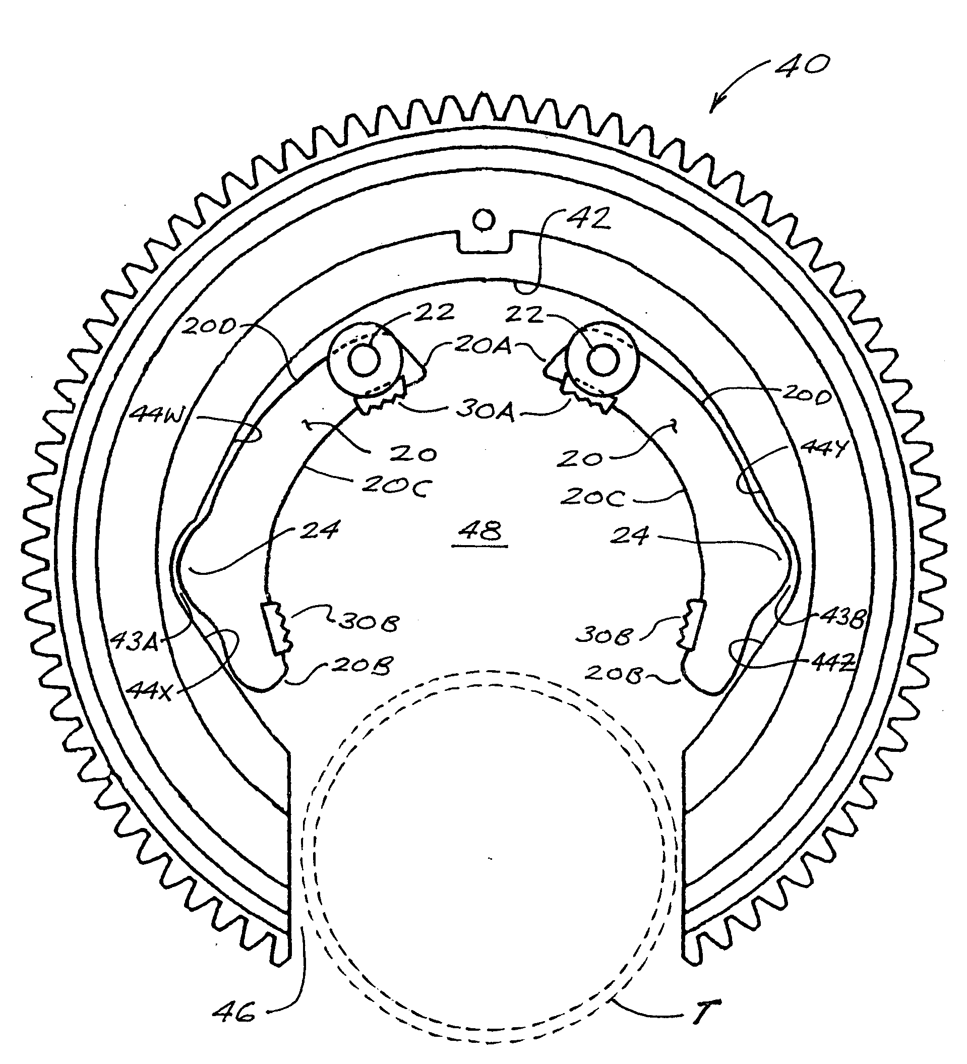
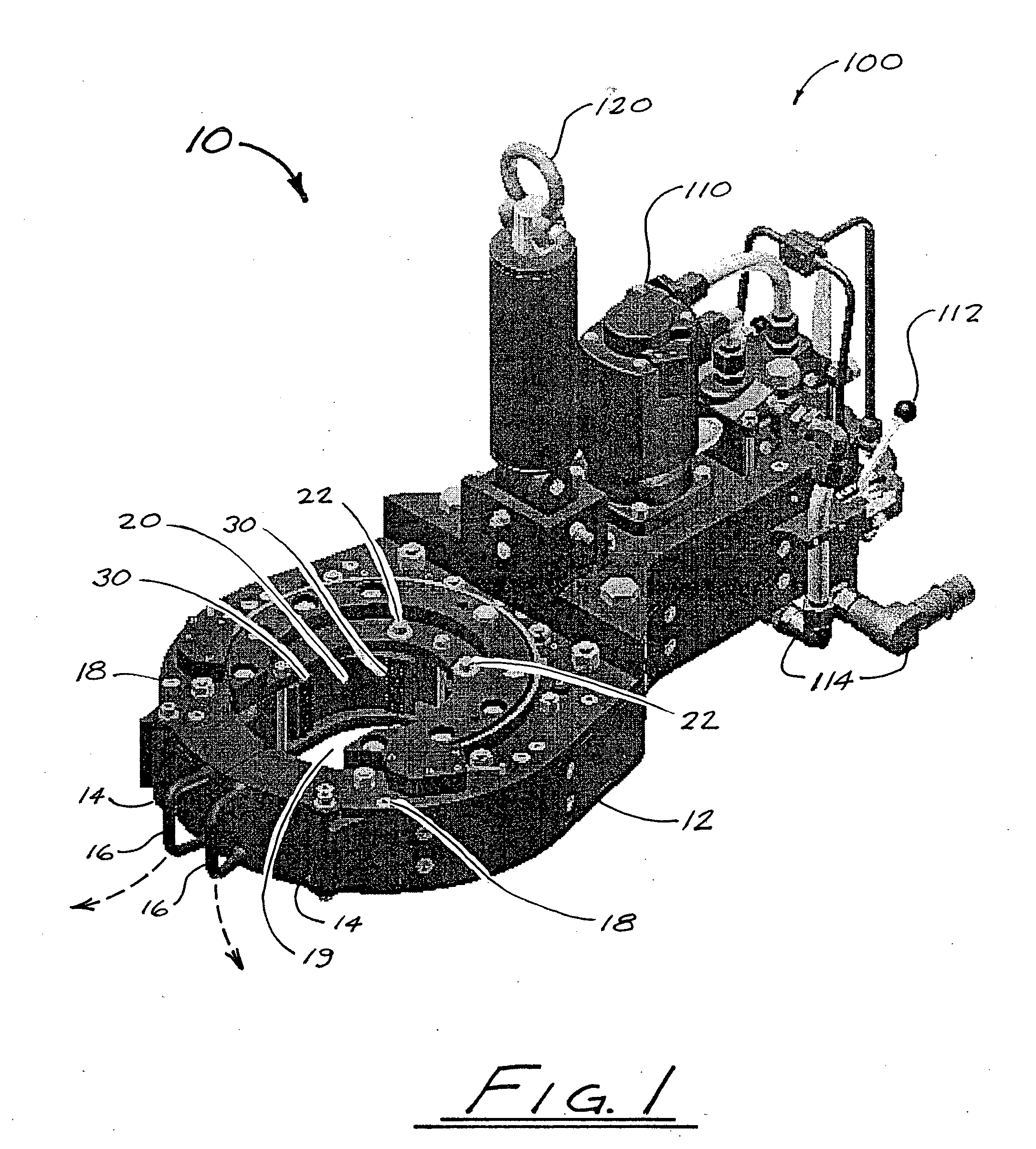
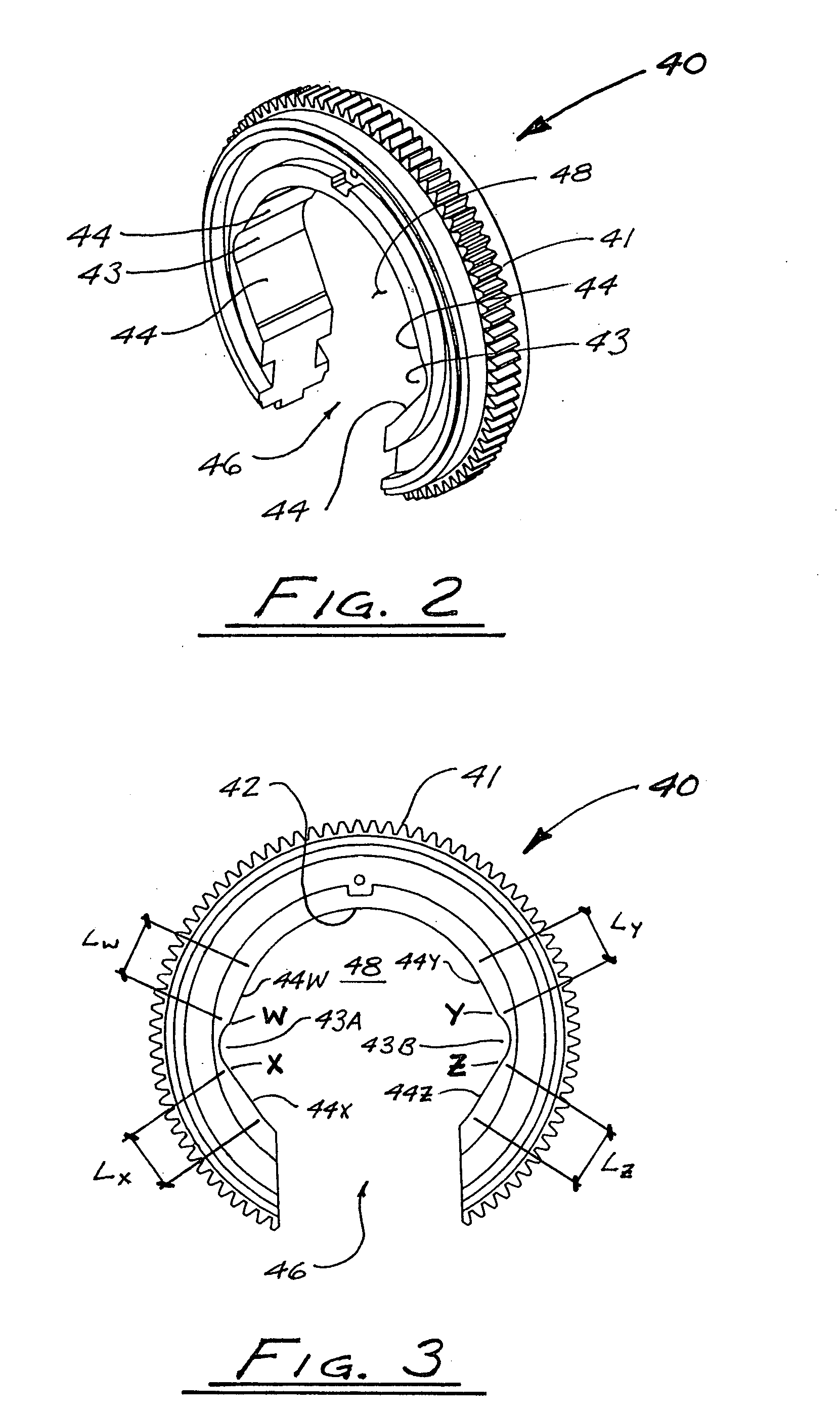
[0037]FIG. 1 generally illustrates an assembled power tong 10 in accordance with one embodiment of the present invention. With the exception of the configuration of the camming surfaces of the rotary gear (which is not visible in FIG. 1), the construction of power tong 10 is largely similar to known power tongs. A generally-C-shaped gear housing 12 has doors 14 which can be swung open about hinge points 18 using handles 16 (as indicated by the broken arrows in FIG. 1) so as to provide an opening into a central space 19 within gear housing 12. A pair of jaw members 20 (typically of generally arcuate shape) are pivotably mounted within gear housing 12. As shown in FIG. 5, each jaw member 20 has a pivot end 20A, a free end 20B, an inner side 20C disposed toward central space 19, and an outer side 20D. The pivot end 20A of each jaw member 20 is pivotably mounted to gear housing 12 by means of a pivot pin 22, at a point opposite the opening into central space 19. Dies 30, for grippingly ...


PUM


Abstract

In a pivoting-jaw power tong, each primary camming surface of the rotary gear has a substantially linear rather than curved configuration. Each primary camming surface forms an acute angle with a radial line extending from the rotary gear centerline to the point where the primary camming surface transitions to its associated neutral recess. Accordingly, the radial distance to a point on any of the primary camming surfaces reduces linearly with increased distance from the neutral recess. Rotation of the rotary gear in either direction away from the neutral position thus results in a linearly progressive reduction in the distance from the center of rotation to the points where the pivoting jaws' cam followers contact the camming surfaces, thus increasing the force exerted by the dies of the jaws upon a tubular disposed within the jaws. This camming surface geometry allows the power tong to automatically adjust for wear in the mechanism such that the contact force between the rollers and the camming surfaces, and the gripping force applied by the dies, will be substantially uniform.

Description

FIELD OF THE INVENTION [0001] The present invention relates in general to power tongs for gripping oilfield tubulars to facilitate make-up or break-out of threaded connections between tubulars. In particular, the invention relates to pivoting-jaw power tongs having rotary gears with improved camming surface geometry. BACKGROUND OF THE INVENTION [0002] Power tongs are well known in the field of drilling and servicing oil and gas wells. Drill pipe and production tubing are typically provided in the form of round steel pipe (commonly referred to as tubulars) with threaded ends for connecting tubulars into a drill string or a production string, depending on the operation being conducted. The term “make-up” is commonly used to refer to the process of connecting tubulars to each other (i.e., “making up” a threaded connection), and the term “break-out” refers to the process of disconnecting tubulars (i.e., “breaking out” a threaded connection). Well drilling and well servicing involve both...

Claims


Application Information

Patent Timeline
Patent Type & Authority Applications(United States)
IPC IPC(8): B25B13/48
CPCE21B19/164
Inventor KATHAN, MURRAY
Owner KATHAN MURRAY
Why Eureka
Try Eureka