Manufacturing apparatus

a technology of manufacturing apparatus and film forming, which is applied in the direction of vacuum evaporation coating, chemical vapor deposition coating, coating, etc., to achieve the effect of higher aperture ratio, higher reliability and higher definition

Inactive Publication Date: 2006-01-19
SEMICON ENERGY LAB CO LTD
View PDF44 Cites 137 Cited by
  • Summary
  • Abstract
  • Description
  • Claims
  • Application Information

AI Technical Summary

Benefits of technology

[0010] A full-color flat panel display using emission colors of red, green, and blue is increasingly required to have higher definition, higher aperture ration, and higher reliability. Such requirements are problems in miniaturizing each display pixel pitch to make a light-emitting device highly precise (increasing the number of pixels) and downsized. Simultaneously, it is also required to improve the productivity and lower the cost.
[0012] The present invention provides a manufacturing apparatus that reduces a manufacturing cost by enhancing efficiency in the use of an EL material and that is provided with a vapor-deposition apparatus which is one of manufacturing apparatuses superior in uniformity in forming an EL layer and in throughput in the case of manufacturing a full-color flat panel display using emission colors of red, green, and blue.
[0013] In addition, the invention provides a vapor-deposition apparatus high in vapor-deposition accuracy capable of miniaturizing each display pixel pitch to make a light-emitting device highly precise (increasing the number of pixels) and downsized.
[0017] Generally, a mask is fixed to a mask frame in a stretched state. In addition, strength of the mask can be maintained by making an opening provided for the mask small. In other words, when tension is applied to the mask by being fixed to the mask frame, the mask can be prevented from cracking from an edge of neighboring openings.
[0020] Further, a step of forming an EL element, in other words, a step of forming an EL layer over a first electrode to a step of forming a second electrode are performed. This is preferably performed with an integrated closed system capable of avoiding impurity contamination, specifically with a multi-chamber system manufacturing apparatus provided with a load chamber, a transfer chamber connected to the load chamber, and a film forming chamber connected to the transfer chamber and having the high vapor-deposition accuracy, or an in-line system manufacturing apparatus.
[0033] Furthermore, a protection circuit (a protection diode or the like) may be provided in the light-emitting device according to the present invention to inhibit electrostatic discharge damage.

Problems solved by technology

Such requirements are problems in miniaturizing each display pixel pitch to make a light-emitting device highly precise (increasing the number of pixels) and downsized.

Method used


Image

  • Manufacturing apparatus
  • Manufacturing apparatus
  • Manufacturing apparatus

Examples


embodiment mode 1

[0055] Hereinafter, an embodiment mode according to the present invention is described.

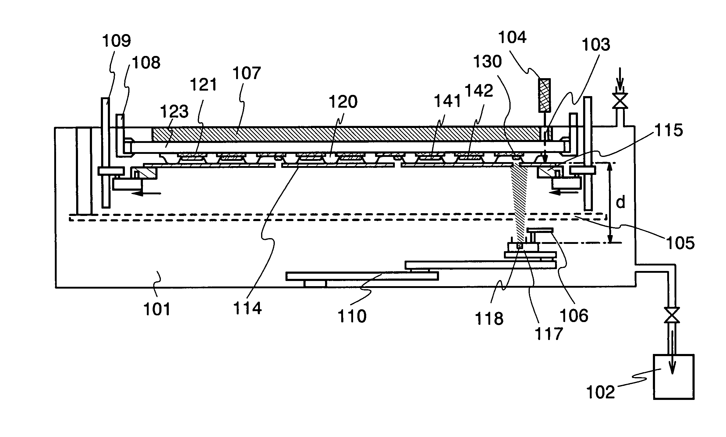
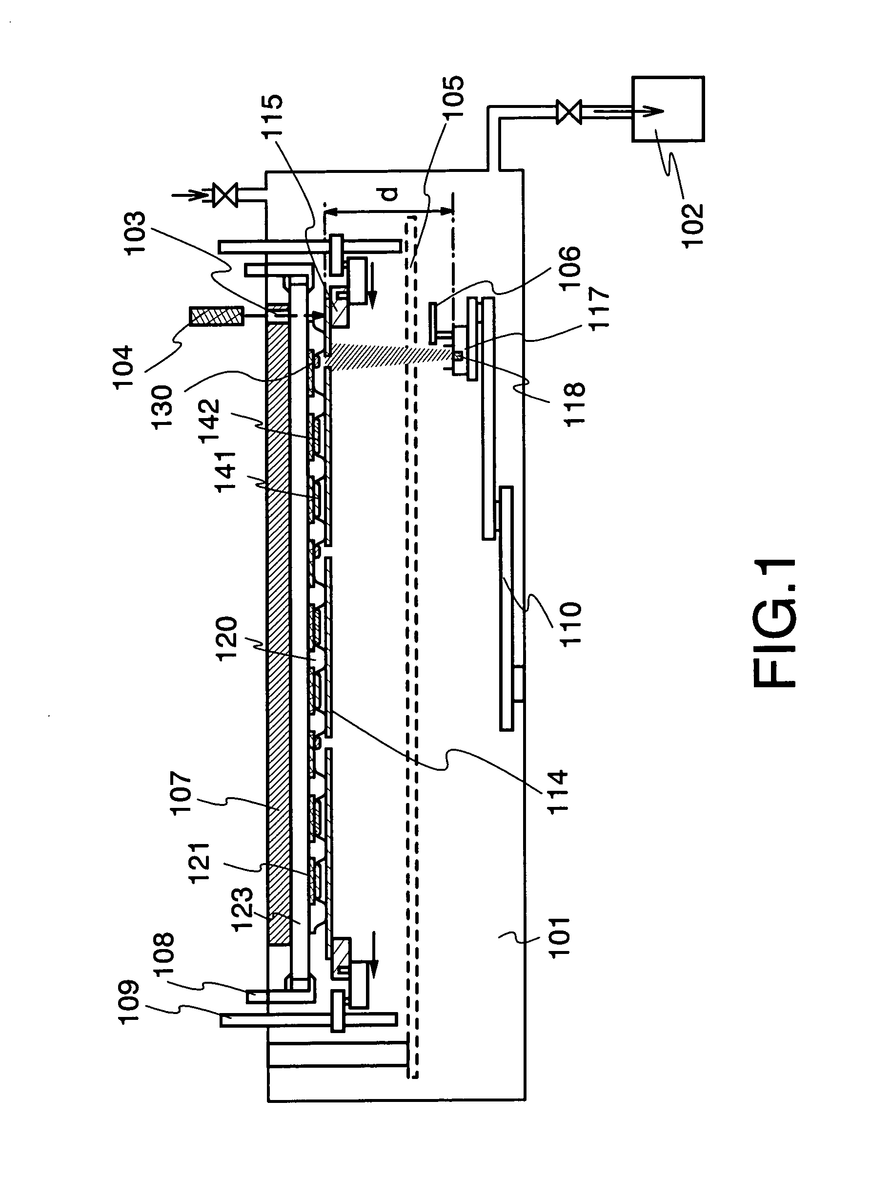
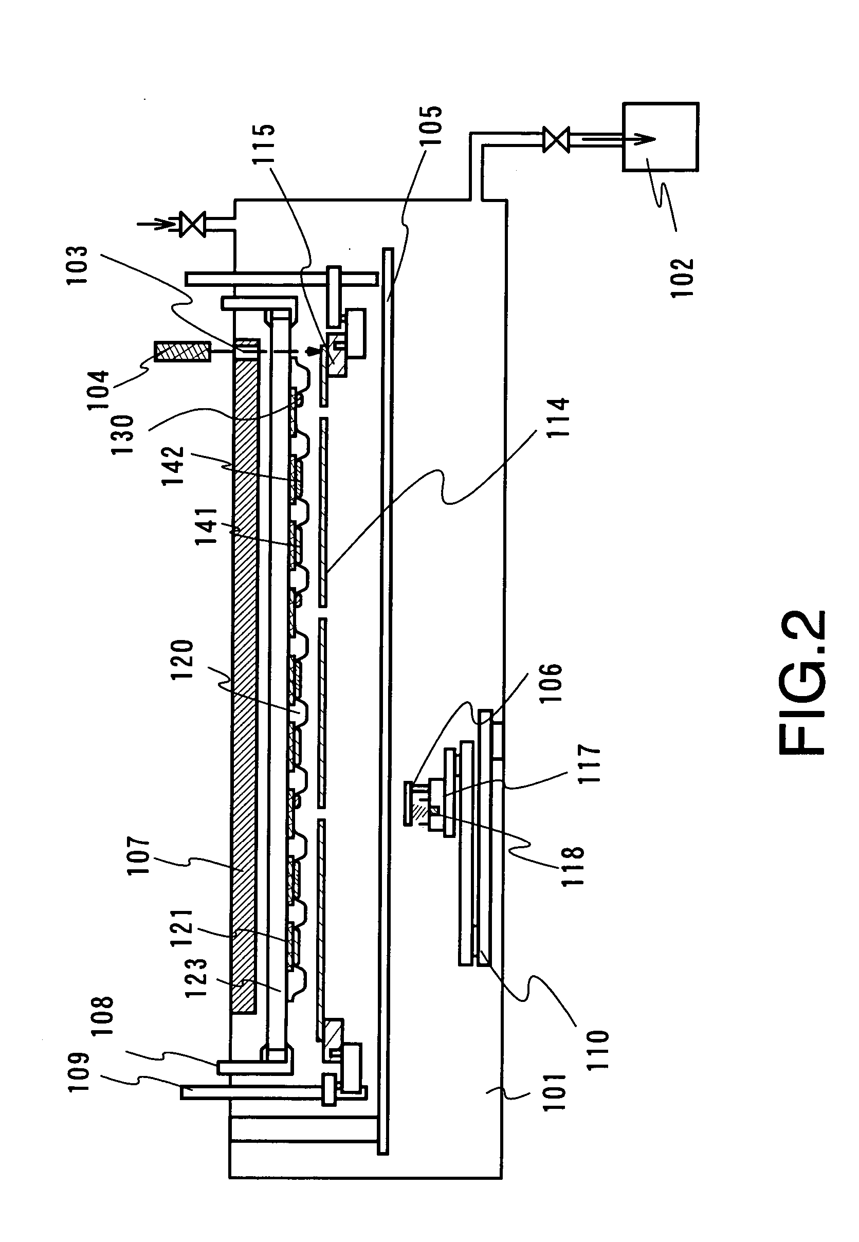
[0056] Here, an example of a vapor-deposition apparatus provided in a film forming chamber with a means for moving a mask and a movement unit for moving a vapor-deposition source holder in an X direction or a Y direction is described with reference to FIG. 1, FIG. 2, FIGS. 3A to 3D, FIGS. 4A and 4B, FIGS. 5A and 5B, and FIGS. 6A and 6B. Note that FIG. 1 shows a cross-sectional view of the vapor-deposition apparatus at the time of vapor-deposition.

[0057] A film forming chamber 101 is provided with a means for reducing the pressure 102 and a means for introducing an inert gas. A magnetic levitation type turbo-molecular pump, a cryo pump, or a dry pump is used as the means for reducing the pressure 102. According to the means for reducing the pressure 102, it is possible to set a reached pressure of a transfer chamber to be 10−5 Torr to 10−6 Torr. In order to prevent impurities from being introduce...

embodiment mode 2

[0089] Hereinafter, a film forming apparatus different from that in Embodiment Mode 1 is described. FIG. 15A shows a cross-sectional view of the film forming apparatus.

[0090] A film forming chamber 301 is provided with a means for reducing the pressure 302, a movement unit 310 of a substrate, a means for moving a mask 309, an imaging means 304, and a nozzle 306.

[0091] The nozzle 306 is provided with seven openings 311 and FIG. 15B shows an example of a top view of the nozzle. As shown in FIG. 15B, a film is formed by moving or shuttling a substrate 323 in the direction of the arrow.

[0092] In addition, the nozzle 306 is connected to a treatment chamber for vaporizing a film forming material 318 by interposing a flow control device 305 such as a mass flow controller or a bulb. This treatment chamber is also provided with a means for reducing the pressure, which is designed to be able to adjust pressure within the treatment chamber. The film forming material 318 is placed in a conta...

embodiment 1

[0107] In this embodiment, FIG. 7 shows an example of a multi-chamber system manufacturing apparatus in which a manufacturing process from the formation of an organic compound formed over a first electrode to the formation of a second electrode to perform sealing is automated. Contamination of impurities such as moisture is prevented and throughput is improved by employing one unit.

[0108]FIG. 7 is a top view of a manufacturing apparatus having transfer chambers 702, 704a, 708, 714, 718, and 747; delivery chambers 705, 707, 711, and 741; a preparation chamber 701; a first film forming chamber 706H; a second film forming chamber 706B; a third film forming chamber 706G; a fourth film forming chamber 706R; a fifth film forming chamber 706E; other film forming chambers 709, 710, 712, 713, and 732; installation chambers 726R, 726G, 726B, 726E, and 726H for providing a vapor-deposition material in a vapor-deposition source holder; a baking chamber 723; pretreatment chambers 703a and 703b;...


PUM

PropertyMeasurementUnit
thicknessaaaaaaaaaa
distanceaaaaaaaaaa
widthaaaaaaaaaa

Abstract

It is an object of the present invention to provide a manufacturing apparatus that reduces a manufacturing cost by enhancing efficiency in the use of an EL material and that is provided with a vapor deposition apparatus which is one of manufacturing apparatuses superior in uniformity in forming an EL layer and in throughput in the case of manufacturing a full-color flat panel display using emission colors of red, green, and blue. According to one feature of the invention, a mask having a small opening with respect to a desired vapor deposition region is used, and the mask is moved accurately. Accordingly, a desired vapor deposition region is vapor deposited entirely. In addition, a vapor deposition method is not limited to movement of a mask, and it is preferable that a mask and a substrate move relatively, for example, the substrate may be moved at a μm level with the mask fixed.

Description

BACKGROUND OF THE INVENTION [0001] 1. Field of the Invention [0002] The present invention relates to a film forming apparatus employed for forming a film of a material capable of forming a film by vapor-deposition (hereinafter referred to as a vapor-deposition material) and a manufacturing apparatus provided with the film forming apparatus. In particular, the invention relates to a vapor-deposition apparatus employed for forming a film by evaporating a vapor-deposition material from a vapor-deposition source provided near a substrate. In addition, the invention relates to a light-emitting device and a manufacturing method thereof. [0003] 2. Description of the Related Art [0004] A Light-emitting element using an organic compound featuring small thickness and weight, fast response, DC low-voltage drive, and the like as a light-emitting substance has been expected to find application in flat panel displays of the next generation. In particular, a display device in which light-emitting ...

Claims


Application Information

Patent Timeline
Patent Type & Authority Applications(United States)
IPC IPC(8): C23C16/00
CPCC23C14/042C23C14/228C23C14/12
Inventor YAMAZAKI, SHUNPEISEO, SATOSHI
Owner SEMICON ENERGY LAB CO LTD
Why Eureka
Try Eureka