Manufacturing method for sintered body with buried metallic member

a technology of metallic body and manufacturing method, which is applied in the direction of turning machines, turning machine accessories, chucks, etc., can solve the problems of large shrinkage, adversely affecting film formation, and fluctuation in film formation, so as to achieve the effect of improving the evenness of the metallic body and reducing shrinkag

Active Publication Date: 2006-01-19
NGK INSULATORS LTD
View PDF3 Cites 72 Cited by
  • Summary
  • Abstract
  • Description
  • Claims
  • Application Information

AI Technical Summary

Benefits of technology

[0010] An object of the present invention is to provide a manufacturing method for a sintered body with a buried metallic member that allows improvement in evenness of the metallic member.
[0012] In this manner, forming the metallic member by printing the printing paste on the alumina sintered body or the alumina presintered body allows little shrinkage due to densification of the alumina compact. Therefore, evenness of the metallic member may be improved.

Problems solved by technology

In addition, for example, when electrode for plasma generation in the ceramic base plate is slanted with respect to the surface of the ceramic base plate, fluctuation in plasma generation occurs, which adversely affects film formation, and thus fluctuation in film formation occurs.
Consequently, shrinkage is great due to deformation at the time of forming the compact and at the time of sintering, namely densification of the compact.
As a result, it is difficult to fulfill the recently desired strict accuracy for evenness.

Method used


Image

  • Manufacturing method for sintered body with buried metallic member
  • Manufacturing method for sintered body with buried metallic member
  • Manufacturing method for sintered body with buried metallic member

Examples


modified example

[0055] Although the inventions have been described above by reference to certain embodiments of the inventions, the inventions are not limited to the embodiments described above. Modifications and variations of the embodiments described above will occur to those skilled in the art, in light of the above teachings.

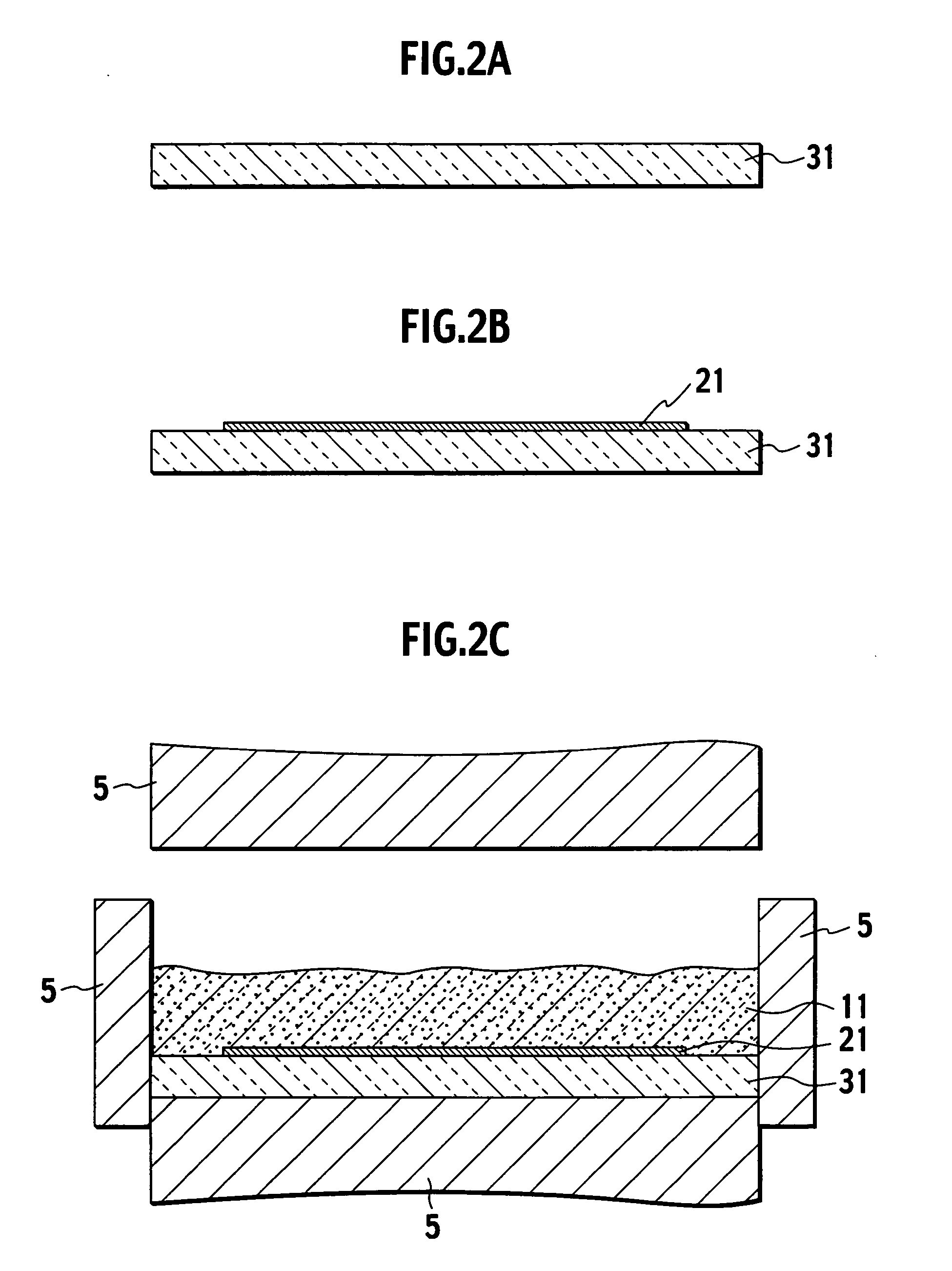
[0056] For example, with the manufacturing method for the electrostatic chuck 10 of the above embodiment, the ceramic base plate 1 is formed by hot press sintering; however, it may be formed by atmospheric sintering, and the alumina sintered body 31, which becomes the ceramic dielectric layer 3, may be sintered by hot press sintering. For example, once the alumina sintered body 31, which becomes the ceramic dielectric layer 3, is provided by hot press sintering, the electrode 2 is formed on a surface thereof by printing or vapor deposition, and the separately formed alumina sintered body, which becomes the ceramic base plate 1, may be adhered to the alumina sintered body 3...

examples

[0061] Working examples of the present invention are described. The present invention is naturally not limited to the following working examples.

[0062] First, a manufacturing method for an electrostatic chuck 10 of working examples 1 through 6 is described. An alumina powder having purity equal to 99.5% (grain diameter 1 ,,m) and a MgO powder, which is a sintering aid, are used as the ceramic powder. Note that the MgO content in the ceramic powder is 0.04% by weight. Polyvinyl alcohol, which is a binder, water, and a dispersant are added to this ceramic powder and mixed for 16 hours using a trommel, forming slurry. The resulting slurry is spray dried using a spray dryer, forming an average of approximately 80 ,,m granules. Next, the granules are inserted in a rubber mold and formed into an alumina compact by a cold isostatic pressing (CIP) apparatus under pressure of 1 ton / cm2. Once this alumina compact is dried, the alumina compact is placed in an alumina case and sintered in an a...


PUM

PropertyMeasurementUnit
melting pointaaaaaaaaaa
flexural strengthaaaaaaaaaa
thickaaaaaaaaaa

Abstract

A manufacturing method for a sintered body with a buried metallic member comprises forming an alumina sintered body or an alumina presintered body, forming a metallic member by printing a printing paste including a refractory metal on the alumina sintered body or the alumina presintered body, forming an alumina compact on the metallic member, and sintering the alumina compact, the metallic member, and the alumina sintered body or the alumina presintered body.

Description

CROSS REFERENCE TO RELATED APPLICATIONS [0001] This application is based upon and claims the benefit of priority from prior Japanese Patent Application No. P2004-164415, filed on Jun. 2, 2004; the entire contents of which are incorporated herein by reference. BACKGROUND OF THE INVENTION [0002] 1. Field of the Invention [0003] The present invention relates to a manufacturing method for a sintered body with a buried metallic member that may be used for semiconductor manufacturing apparatus or the like. [0004] 2. Description of the Related Art [0005] Currently, semiconductor manufacturing apparatus such as a heater, which heats a semiconductor wafer, an electrostatic chuck, which adsorbs and holds the semiconductor wafer, or a susceptor, which is applied a high-frequency voltage, is used in a semiconductor manufacturing process. Dense ceramics such as aluminum nitride, silicon nitride or alumina are noticeable as base materials for such semiconductor manufacturing apparatus. [0006] Wit...

Claims


Application Information

Patent Timeline
Patent Type & Authority Applications(United States)
IPC IPC(8): B28B1/00C04B41/90B32B18/00C04B35/111C04B35/645C04B41/00C04B41/45C04B41/50C04B41/51C04B41/52C04B41/89H01L21/00H01L21/02H01L21/683H05B3/14
CPCC04B35/111Y10T279/23C04B35/62665C04B35/63C04B35/634C04B35/6455C04B41/009C04B41/52C04B41/89C04B2235/3206C04B2235/604C04B2235/96C04B2235/963C04B35/62655C04B41/4539C04B41/4572C04B41/5133C04B41/5057C04B41/522C04B41/5031C04B41/0072C04B41/4521C04B41/4545C04B35/10C04B35/645
Inventor MATSUDA, HIROTONOBORI, KAZUHIROMORI, YUTAKA
Owner NGK INSULATORS LTD
Why Eureka
Try Eureka