

Linear motor for use in machine tool
a linear motor and machine tool technology, applied in the direction of dynamo-electric machines, electrical apparatus, magnetic circuits, etc., can solve the problems of reducing processing accuracy, limiting high-speed processing, and limiting speed at about 20 m/minute at fast forward speed, so as to achieve significant reduction of cogging force, increase the speed of processing, and increase the effect of thrus
- Summary
- Abstract
- Description
- Claims
- Application Information
AI Technical Summary
Benefits of technology
Problems solved by technology
Method used
Image

Examples
example 1
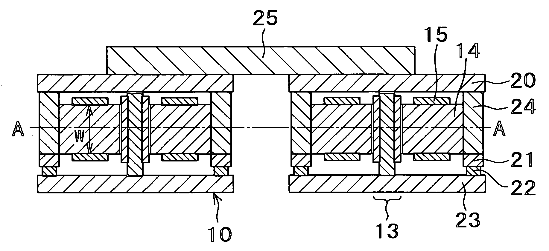
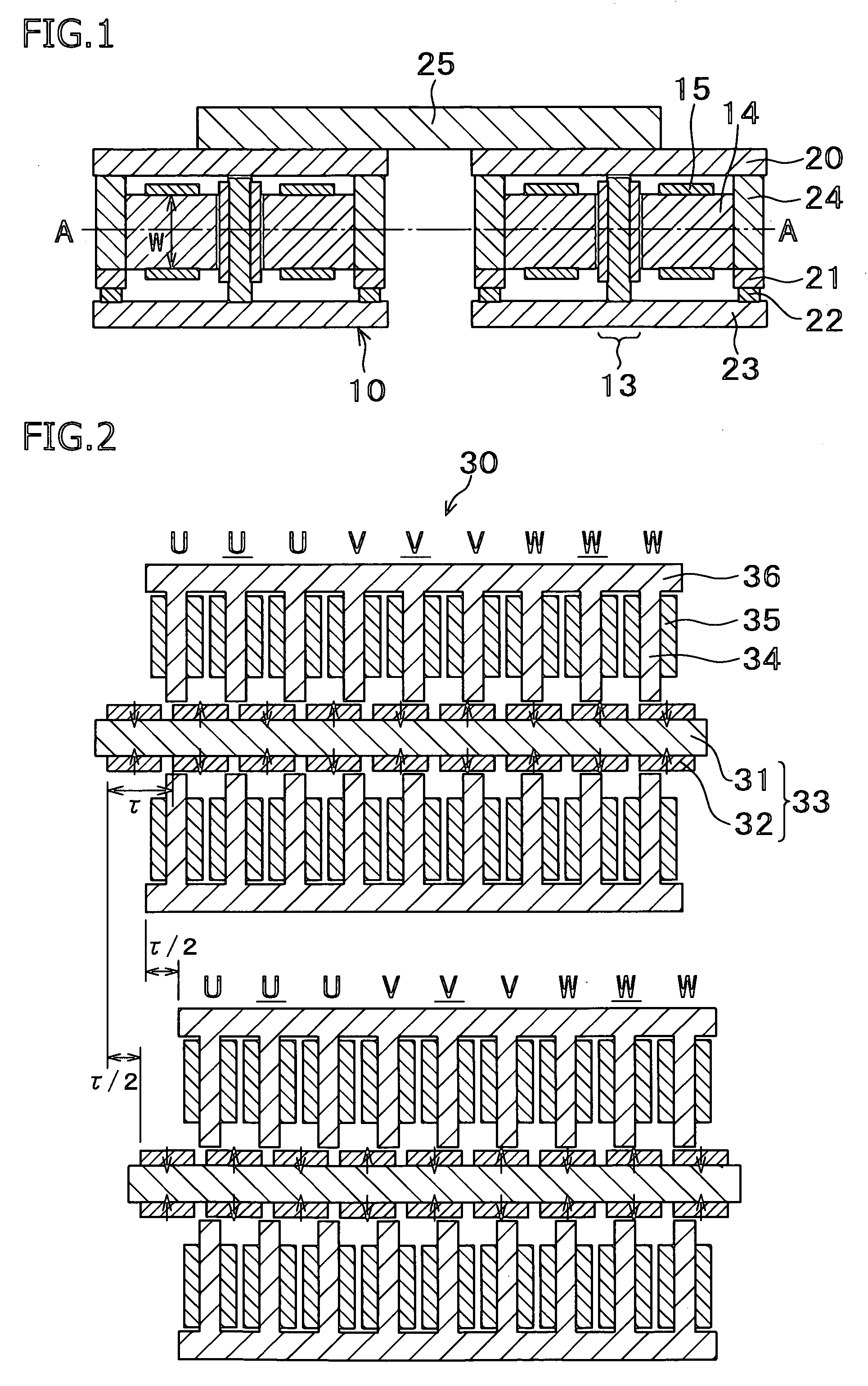
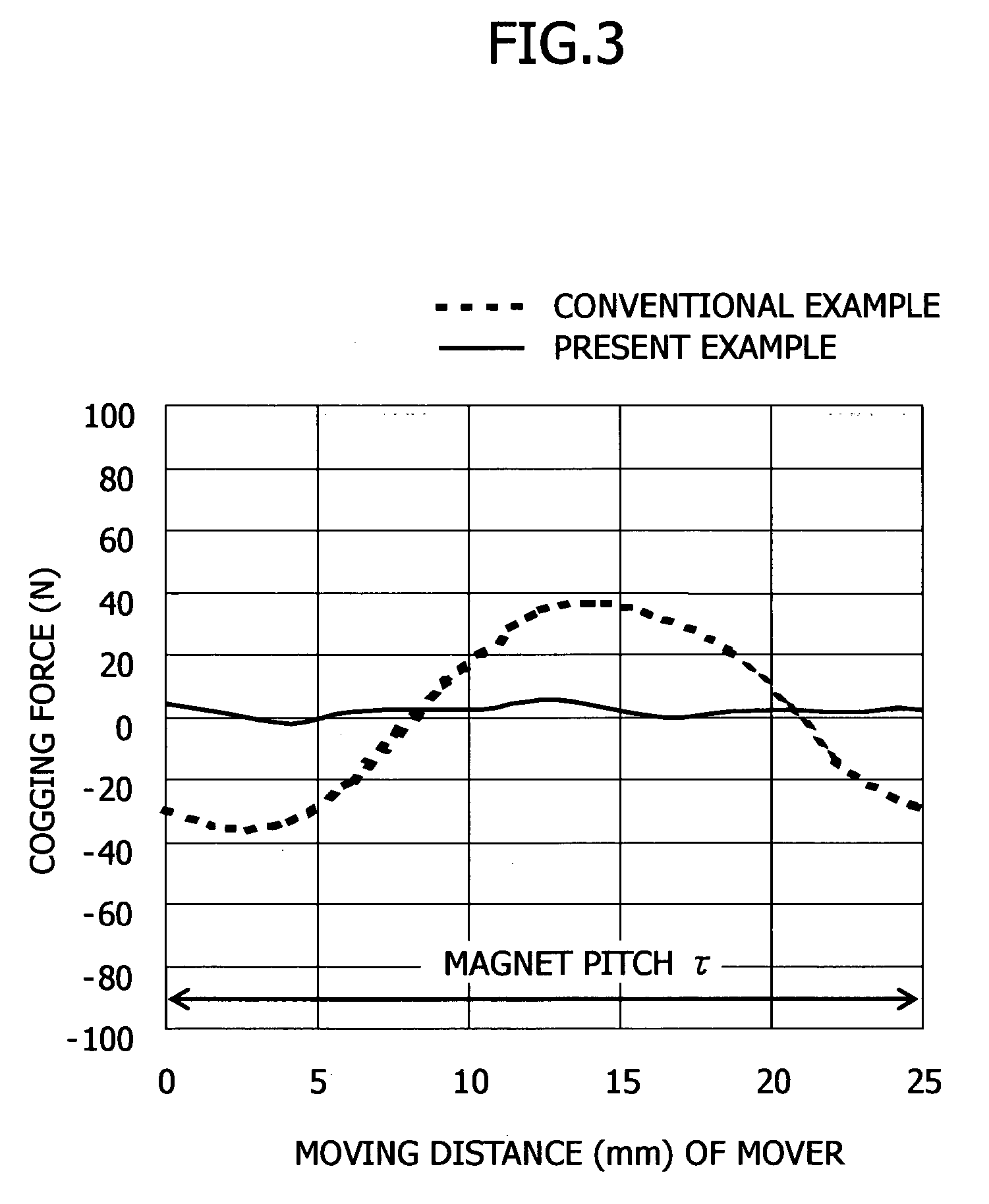
[0068] The linear motor 30 shown in FIG. 2, in which two linear motor units were disposed in parallel such that a second linear motor unit was displaced in the moving direction by ½ of the magnet pitch, which corresponds to 180° of the waveform of the cogging force, was used. A Nd—Fe—B based permanent magnet was used, and an iron yoke was used as the core material. Regarding the section sizes in FIG. 2, the width of the magnets was 18 mm, the thickness of the magnets in the magnetization direction was 5 mm, the magnet pitch was 25 mm, the width of the teeth of the armature cores was 10 mm, the length of the teeth was 34 mm, and the thickness of the stator yoke was 19 mm. The gap between the movers and the stator magnets was 1 mm. The movers and the stators had a thickness of 50 mm in the cross-sectional direction. A solid line in FIG. 3 shows the results. As shown in the drawing, the cogging force of the present invention was reduced, and the difference between the maximum and minim...
example 2
[0069] The linear motor 40 shown in FIG. 4, in which two linear motor units were disposed in parallel and magnetic cores (auxiliary cores) were provided in each linear motor unit, was used, and the magnetic flux distribution was adjusted by changing the difference ΔH between the face of the auxiliary cores and that of the armature cores (main cores). A Nd—Fe—B based permanent magnet was used, and an iron yoke was used as the core material. Regarding the section sizes in FIG. 4, the width of the magnets was 18 mm, the thickness of the magnets in the magnetization direction was 5 mm, the magnet pitch was 25 mm, the width of the teeth of the armature cores was 10 mm, the length of the teeth was 34 mm, and the thickness of the stator yoke was 19 mm. The gap between the movers and the stator magnets was 1 mm. The movers and the stators had a thickness of 50 mm in the cross-sectional direction. As shown in FIG. 5, as the difference ΔH increases, the cogging force decreases, and when ΔH=8 ...
example 3
[0070] The linear motor 50 shown in FIG. 6, in which two linear motor units were disposed in parallel and each linear motor unit comprised two mover blocks wherein the spacing between the two blocks was ½ of the magnet pitch, was used. A Nd—Fe—B based permanent magnet was used, and an iron yoke was used as the core material. Regarding the section sizes in FIG. 6, the width of the magnets was 18 mm, the thickness of the magnets in the magnetization direction was 5 mm, the magnet pitch was 25 mm, the width of the teeth of the armature cores was 10 mm, the length of the teeth was 34 mm, and the thickness of the stator yoke (iron plate) was 19 mm. The gap between the movers and the stator magnets was 1 mm. The length of the spacer (non-magnetic stainless steel, SUS 304) between the first and second blocks was 12.5 mm. The movers and the stators had a thickness of 50 mm in the cross-sectional direction. Regarding the cogging force at this time, the difference between the maximum and mini...
PUM
 Abstract
Description
Claims
Application Information